M1109 Combo Lathe/Mill
OPERATIONS
Setting RPM
To determine and set the needed cutting RPM, do these steps:
1.Use the table in Figure 37 to determine the cutting speed required for the workpiece material.
2.Determine the average final diameter of the workpiece in inches, for the cut to be made.
Failure to follow RPM and feed rate guidelines may threaten operator safety from ejected parts or bro- ken tools.
3.Now use the following formula to determine the clos- est RPM for the cutting operation:
(Cutting Speed x 4) = RPM
Diameter of Cut
4.With the calculated RPM, decide on the closest cut- ting RPM to what you need.
5.Make sure the spindle is completely stopped before proceeding.
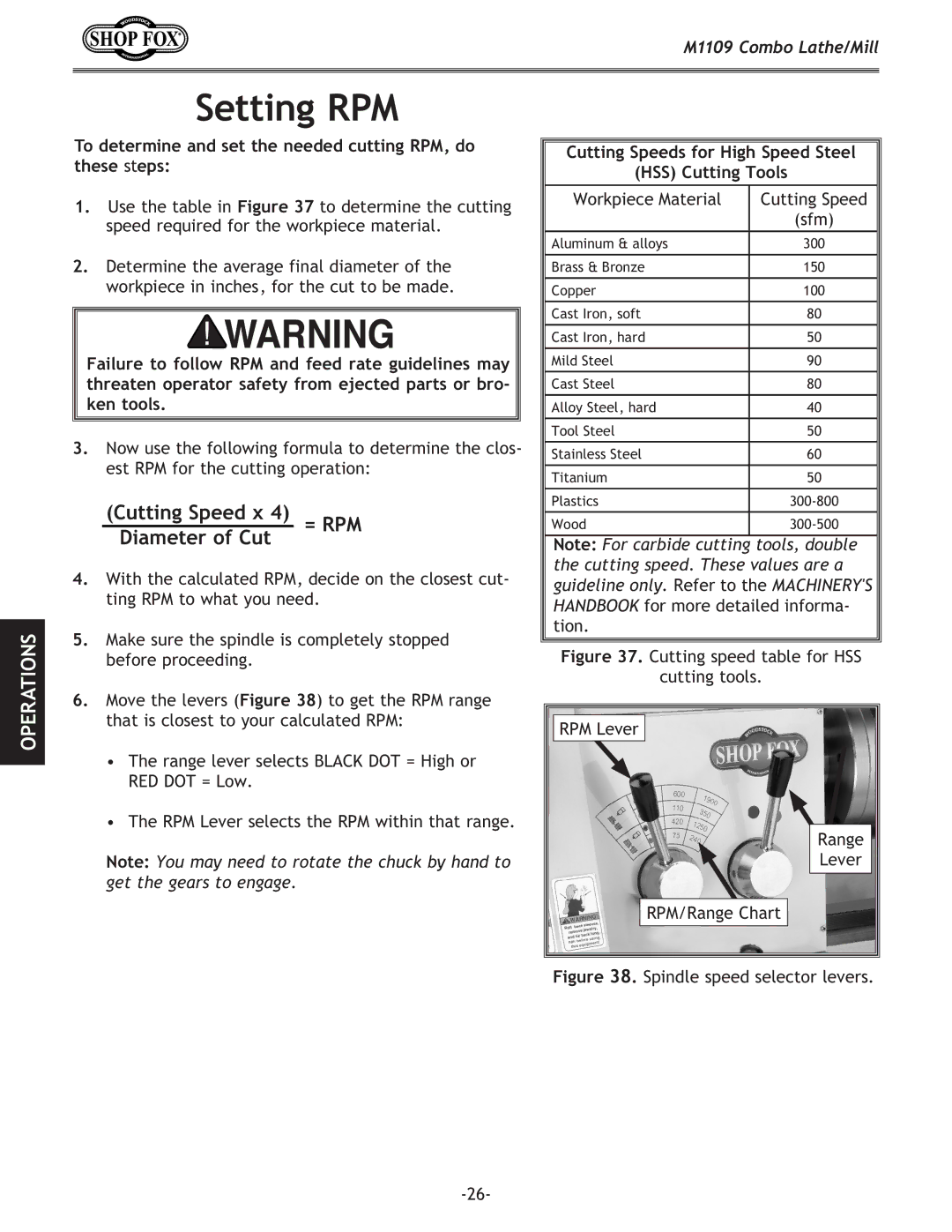
6.Move the levers (Figure 38) to get the RPM range that is closest to your calculated RPM:
•The range lever selects BLACK DOT = High or RED DOT = Low.
•The RPM Lever selects the RPM within that range.
Note: You may need to rotate the chuck by hand to get the gears to engage.
Cutting Speeds for High Speed Steel
(HSS) Cutting Tools
Workpiece Material | Cutting Speed |
| (sfm) |
Aluminum & alloys | 300 |
|
|
Brass & Bronze | 150 |
|
|
Copper | 100 |
|
|
Cast Iron, soft | 80 |
|
|
Cast Iron, hard | 50 |
|
|
Mild Steel | 90 |
|
|
Cast Steel | 80 |
|
|
Alloy Steel, hard | 40 |
|
|
Tool Steel | 50 |
|
|
Stainless Steel | 60 |
|
|
Titanium | 50 |
|
|
Plastics | |
Wood |
Note: For carbide cutting tools, double the cutting speed. These values are a guideline only. Refer to the MACHINERY'S HANDBOOK for more detailed informa- tion.
Figure 37. Cutting speed table for HSS
cutting tools.
RPM Lever |
Range |
Lever |
RPM/Range Chart |