Troubleshooting Reference
WARNING: Electrical shock and burn hazard
Do not disassemble the Freedom HF. It does not contain any
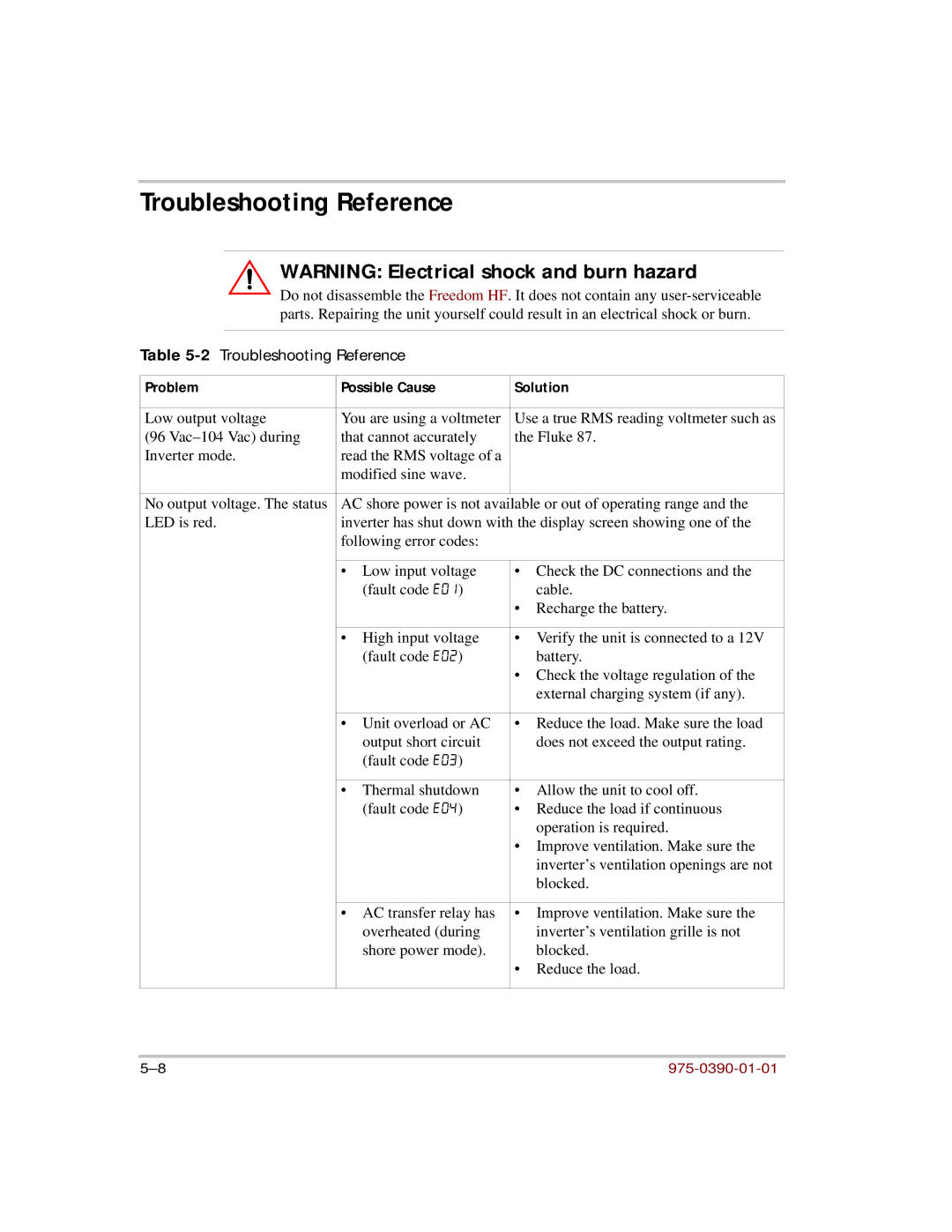
Table 5-2 Troubleshooting Reference
Problem | Possible Cause | Solution | ||
|
|
| ||
Low output voltage | You are using a voltmeter | Use a true RMS reading voltmeter such as | ||
(96 | that cannot accurately | the Fluke 87. | ||
Inverter mode. | read the RMS voltage of a |
|
| |
| modified sine wave. |
|
| |
|
|
| ||
No output voltage. The status | AC shore power is not available or out of operating range and the | |||
LED is red. | inverter has shut down with the display screen showing one of the | |||
| following error codes: |
|
| |
|
|
|
| |
| • | Low input voltage | • Check the DC connections and the | |
|
| (fault code E01) |
| cable. |
|
|
| • | Recharge the battery. |
|
|
|
| |
| • | High input voltage | • Verify the unit is connected to a 12V | |
|
| (fault code E02) |
| battery. |
|
|
| • Check the voltage regulation of the | |
|
|
|
| external charging system (if any). |
|
|
| ||
| • Unit overload or AC | • Reduce the load. Make sure the load | ||
|
| output short circuit |
| does not exceed the output rating. |
|
| (fault code E03) |
|
|
|
|
|
| |
| • | Thermal shutdown | • Allow the unit to cool off. | |
|
| (fault code E04) | • Reduce the load if continuous | |
|
|
|
| operation is required. |
|
|
| • Improve ventilation. Make sure the | |
|
|
|
| inverter’s ventilation openings are not |
|
|
|
| blocked. |
|
|
| ||
| • AC transfer relay has | • Improve ventilation. Make sure the | ||
|
| overheated (during |
| inverter’s ventilation grille is not |
|
| shore power mode). |
| blocked. |
|
|
| • | Reduce the load. |
|
|
|
|
|