IP1012 AL specifications
The Xantrex Technology IP1012 AL is a high-performance inverter designed to meet the needs of mobile and off-grid applications. With its compact and lightweight design, the IP1012 AL is ideal for recreational vehicles, boats, and even remote cabins, providing a reliable source of power wherever it is needed. One of the standout features of this inverter is its ability to deliver a continuous output of 1000 watts, with a surge capacity of up to 2000 watts. This makes it capable of powering a range of devices, from laptops and televisions to small appliances and power tools.The Xantrex IP1012 AL utilizes advanced sine wave technology, which produces a pure sine wave output that is essential for sensitive electronic equipment. This technology ensures that devices such as computers and medical equipment operate safely and efficiently, minimizing the risk of damage from power fluctuations. Additionally, the inverter is equipped with built-in safety features, including thermal shutdown protection, overload protection, and short circuit protection, ensuring that both the inverter and connected devices are safeguarded against potential electrical hazards.
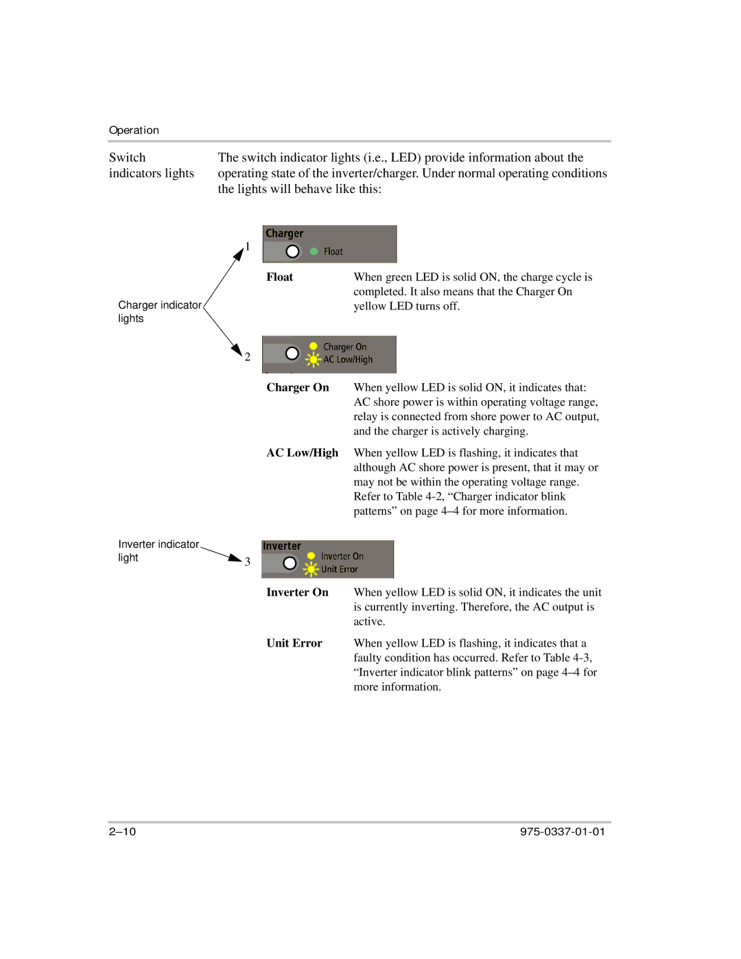
Another key characteristic of the IP1012 AL is its user-friendly interface, featuring LED indicators that provide real-time information on the inverter's status and performance. The inverter also boasts a wide input voltage range, accommodating various battery types and configurations, making it versatile and adaptable for different applications. Its lightweight aluminum chassis further enhances its portability, making it a perfect choice for outdoor enthusiasts and those seeking a dependable power source for camping or hiking trips.
Furthermore, the Xantrex IP1012 AL is designed for efficiency, with a built-in energy-saving mode that reduces power consumption when the inverter is not in use. This feature prolongs battery life and maximizes the efficiency of the overall system. The inverter connects easily to battery banks, and its compact form factor allows for convenient installation in tight spaces.
In summary, the Xantrex Technology IP1012 AL is a powerful and reliable inverter that offers essential features for a variety of mobile and off-grid applications. Its advanced sine wave technology, safety features, user-friendly interface, and energy efficiency make it an excellent choice for anyone looking for dependable portable power. Whether you're a weekend warrior or a full-time RV traveler, the IP1012 AL ensures you have the energy you need when you need it.

