SW Series Inverter/Chargers
2001 Xantrex Technology, Inc Telephone 360/435-8826
Product Materials Package
2001 Xantrex Technology, Inc Telephone 360/435-8826
Table of Contents
Operation
137
128
135
Index of Figures
131
Table of Contents Index of Tables
Important Safety Instructions
General Precautions
Special Notices
Personal Precautions
Important Safety Instructions
Introduction
Introduction
Unit Identification
Model Number
Unit Identification
Display
CONTROLS, Indicators and Components
Control Panel
Reset to Factory Defaults Button
LED Status Indicators
Contrast Control
Menu Buttons
Error Red
AC1 in Good Green
AC2 in Good Green
Bulk Yellow
AC Side
Remote Port
Stacking Port
INVERTER/CHARGER Circuit Breaker
Internal Components and Indicators
LED Indicators
BTS Port
AC Terminal Block
Battery Terminals DC Equipment Ground
AC Safety Ground
Auxiliary and Generator Control Relay Connectors
DC Side
Installation
Quick Install
Location
Complete Install
Unpacking
AC Input and Output Connections
AC Wiring
Ventilation
AC Terminal Block # Wire Color
AC OUT
AC Connections
Purpose
External Transfer Relays
AC Installation Guidelines
Important Precaution
VAC Ground Fault Interrupt Outlets GFI’S
Pass & Seymor
DC Wiring
Battery Cable Sizing
Inverter Model Typical AMPS1 NEC To 3 Feet
To 5 FT
DC Disconnect and Overcurrent Protection
Cable Size Required
Rating Maximum Conduit Breaker Size Free AIR
Maximum Fuse Size
Battery Cable Connections
Installation Procedure Battery Cables
Control Wiring
GEN Control Wiring
AUX Relay Wiring
Remote Control Wiring
System Grounding
Equipment or Chassis Grounds
Grounding ELECTRODES/GROUND Rods
Bonding the Grounding System
NEUTRAL-TO-GROUND Bond Switching RV and Marine Applications
NEUTRAL-TO-GROUND
AC Source
AC Source
Keep Equipment Close Together
Grounding VS. Lightning
ONE Ground for ALL Equipment
Installation
Functional Test
Functional Test
Menu System
Overview
User Menu MAP
Push buttons on
Setup Menu MAP
FLT Sell SLT LBX
User Menu
Menu Headings
Information Display
Inverter Mode 1 Menu Heading
Generator Mode 2 Menu Heading
Gen under/over SpeedNO
Trace Engineering 3 Menu Heading
5916 195th St NE Arlington, WA 98223 USA Fax
Meters 4 Menu Heading
Error Causes 5 Menu Heading
High Battery VoltageNO
Generator Timer 7 Menu Heading
Time of DAY 6 Menu Heading
Setup Menu
Inverter Setup 9 Menu Heading
VDC models Range 08.0 to
Battery Charging 10 Menu Heading
Battery temperature if the BTS sensor is installed
AC Inputs 11 Menu Headings
GEN Auto Start Setup 12 Menu Heading
GEN Starting Details 13 Menu Heading
Auxiliary Relays 14 Menu Heading
VDC Models Range 00.1 to
Bulk Charge Trigger Timer 15 Menu Heading
LOW Battery Transfer 16 Menu Heading
Battery Selling 17 Menu Heading
Grid Usage Timer 18 Menu Heading
Information File Battery 19 Menu Heading
Menu System
Operation
Theory of Operation
Trace SW Series Inverter Output Waveform
Power VS. Efficiency
Efficiency
Inverter Capacity VS Temperature
Power Capacity
Temperature C
Total
Additional Features
Operating Modes
Inverter Mode
Search Mode Control
Batterydc Inverter AC Loads
Setting Search Mode Watts
Adjusting the LOW Battery Protection
LOW Battery Protection
Setting Search Mode Spacing
Three Stage Charging Process
Charger Mode
AC Source Charger Battery
Battery Temperature Sensor BTS
Charger only Operation
AC Input Requirements
Input AC Voltage
Recommended Battery Charger Settings
Delay Period
AC Current Level
Frequency
Typical Bulk and Float Setpoints for Common Battery Types
Equalizing Batteries Unsealed or Vented Batteries only
Operation
INVERTER/CHARGER Mode
Utility Grid Generator INVERTER/ Charger AC Loads Battery
Transferring Upon Availability of AC Power
Transferring Based on Battery Voltage
Transfer Time
Generator Support Mode
Generator Inverter Charger Battery AC Loads
Generator SUPPORT/OVERLOAD Protection
VAC VS /240 VAC Generators
Automatic Generator Control Mode
Generator Control INVERTER/ Charger AC Loads Battery
Automatically
GEN Control Relays
Generator Starting Scenarios
Generator Starting and Stopping Configurations
Manually
TWO Wire Start Generators
Wire Type Generator
Generator Auto Start Requirements and Types
GEN Control Relays
THREE-WIRE Start Generators
Honda Type Generator
TO-2 Wire Converters
Generator Control Sequence
Generator Error Causes
Generator Stop Cool Down Period
Equalization CHARGING, Automatic Generator Control System
Utility Backup Mode
Utility SUPPORT/OVERLOAD Protection
Using SLT Mode Silent Mode
Battery Requirements
KWh Meter
Utility Interactive Mode
Utility Grid
Theory of Operation
Utility Interactive Islanding Protection
Selling Power from a DC Charging Source
Time DC Volts
Selling Power Stored in the Batteries
Time
Battery Regulation Level Sell Mode
Utility Interactive Operation with Utility Backup
Backup of Critical AC
Utility Interactive
LINE-TIE System with
Overvoltage Protection for the Battery in Sell Mode
Battery Bank
Solar Array
SW Series
Energy Management Mode
INVERTER/ Charger Battery AC Loads
Operation
Peak Load Shaving Mode
Brief
LOW Battery Transfer LBX Mode
Utility Grid kWH Meter
Operation
Series Stacked Operation
Using Multiple Inverters
INPUT/OUTPUT Bypass Breaker Switch 240 VAC Loads
240 VAC/60 HZ only Electrical Systems
Generator Control Settings
Parallel Stacked Operation
Battery Charging with Multiple Inverters
Automatic Generator Control with Multiple Inverters
Operation
Technical Information
Battery Type
Selection of Battery Type
Sealed Lead Acid Batteries
Nicad and Nickel Iron Nife Battery
100
Battery Sizing
Estimating Battery Requirements
101
Typical Appliance Watts
102
Battery Bank Sizing
Example
Worksheet
103
Battery Care and Maintenance
104
105
Monthly Maintenance
Battery State of Charge
Battery Installation
Battery Enclosures
Battery Temperature
106
Battery HOOK-UP Configurations
Series Connection
107
48V Inverter
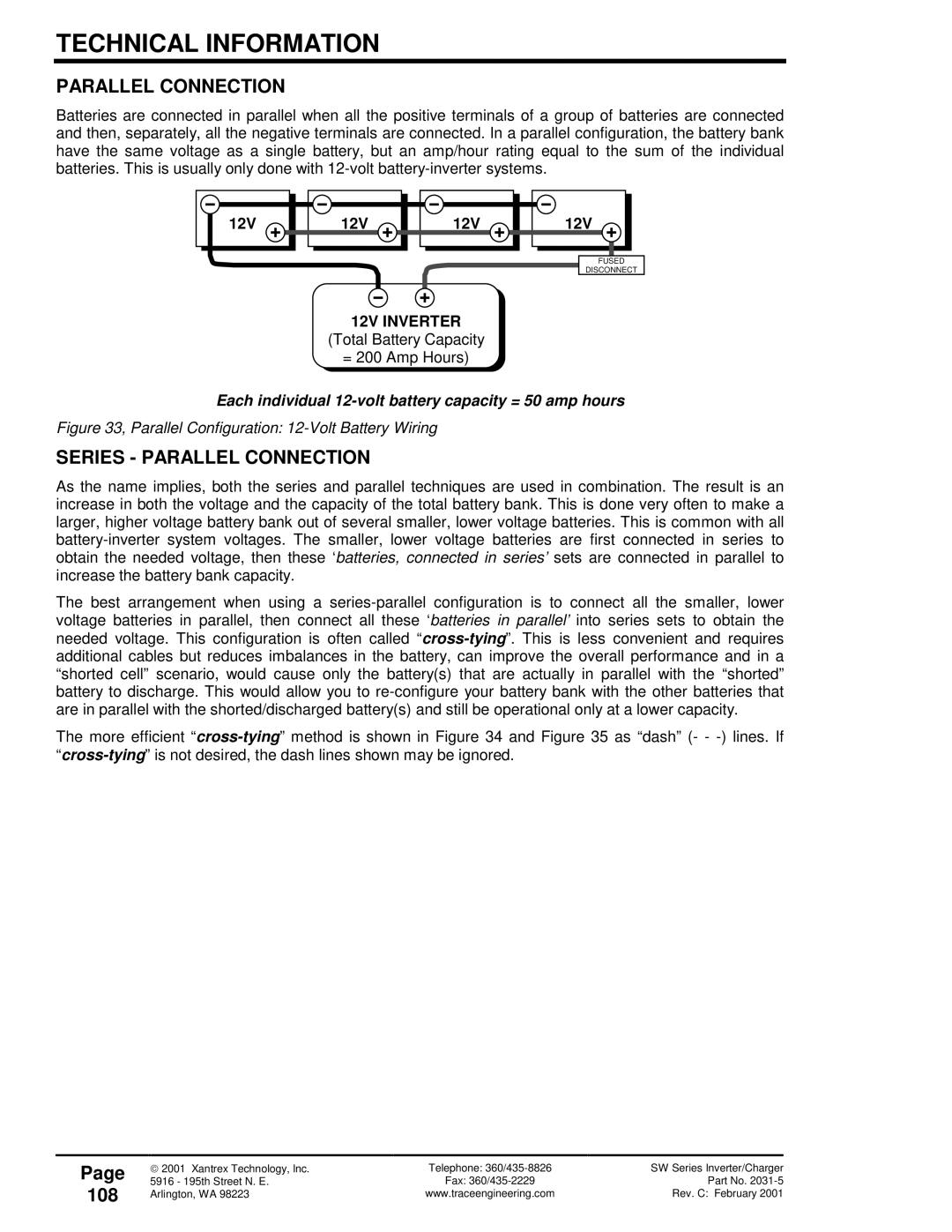
Parallel Connection
Series Parallel Connection
108
12V Inverter
Total Battery Capacity
109
24V Inverter
= 200 Amp Hours
110
Battery Cable Inductance
Distance Between Battery Cables Inductance Micro-Henries
Applications
Resistive Loads
Inductive Loads
111
Troubleshooting Guide
Problem
Solution
112
Problem Indication Solution
113
Indication Solution
114
Digital VoltMeter DVM
INVERTER/CHARGER Terminology
115
116
AC Waveforms
117
Stacking
Specifications and Features 60 Hz Models
118
Specifications and Features 50 Hz Models
119
Dimensions
120
Installation Diagrams
121
122
User Settings Worksheets
User Menu
123
SW Series Inverter/Charger Model SW
Setup Menu 12 VDC 120 VAC/60HZ Models
124
Setup Menu 24 VDC 120 VAC/60HZ Models
125
Setup Menu 48 VDC 120 VAC/60HZ Models
126
127
Appendix
Options
Swrc
Swca
Other Products
Reference Tables and Graphs
130
AWG Wire Size
131
132
Inverter Model
Cable Size Required Free AIR
Knockout or Hole Diameter Inches
Preparation for Storage
133
Interior Storage
Exterior Storage
134
WARRANTY/REPAIR Information
Limited Warranty
Warranty Registration
Life Support Policy
Warranty or Repair Service Required
136
Index
137
Fusing 25, 74
138
139
Equalization Charging 38, 47, 68, 79, 80
Menu 4 Meters Menu 5 Error Causes
140
141
Set Input Lower Limit VAC 71, 72
142