Xerox
Page
Installation caution
Safety
Canada
Laser safety
Europe 50 Hz, 220 240 V equipment
Avoid Direct Exposure to Beam
50hz. Configuration 60hz. Configuration
Operational safety
Do this
Do not do this
Approvals and certification
Safety feature
Configuration of ELCI/RCD Window Reset button
60 Hz, 115
International configuration of ELCI/RCD Window Reset button
Page
Table of contents
Function Selection via Line FSL commands
Xiii
Xiv
Error handling
Configuration and sysgen samples
Font support and selection
Configuration and Resource Utility MVS
Appendices
GLOSSARY±1
Glossary
Index
INDEX±1
Page
About this manual
Conventions
Text conventions
Enter print
Procedure conventions
GSM
Bold
Procedure conventionsÐpersonal computer PC
Window messages
Keyboard key
Page
Overview and printer setup
Emulated printers
CPI LPI
Xerox printer
Printer Model Type Speed
Character sets
Features and compatibilities
Printer setup
MRP Family user interface interaction with coax interface
Print Language Setup HP LaserJet Emulation Mode
For A4 paper use
Sets the default print language
Configuring the Coax interface card
Sets the default paper size
ST1
Print language
Checking the interface configuration
Size
Printer address and emulation
Sample of a Coax Interface Configuration Report
FSL cross reference for the coax configuration
Command Numbers and names
MRP Family delete current job capability
Data stream commands
DSC control codes
Command summary and comparison
End of Message EM
DSC command descriptions
Carriage Return CR
Form Feed FF
Null NUL
Reserved codes
Command summary
SCS data stream structure
Supported SCS commands
SCS command comparison
Command descriptions
Back Space BS
SCS coax
Enable Print ENP
Bell BEL
Inhibit Print INP
Graphic Escape GE
Horizontal Tab HT
Remember
Interchange Record Separator IRS
Line Feed LF
Presentation Media PPM
2BD2nn48xxxxxxsddoddxxxxxxxx
Color definitions
Set Attribute SA
Extended highlighting definitions
Character Set definitions
Set Graphic Error Action Sgea
2BC803grop
Set Horizontal Format SHF
2BC1nnhhlmrmht...tn
One-byte number that specifies the column
Set Line Density SLD
Set Print Density SPD
Set Vertical Format SVF
2BC2nnvvvtmbmvt1...tn
One-byte number that specifies the first print
Transparent TRN
Vertical Channel Select VCS
Vertical Tab VT
Page
Setting levels
Storing and reading settings
Actions at power up
Function Selection via Line FSL
Types of FSL escape character
Using FSL escape character
FSL escape character
Permanent
Format of FSL escape sequences
Removing FSL escape character
FSL types
General syntax of an FSL command
FSL commands
FSL
Set IBM Buffer Size
FSL
Common command features
ESCÐSingle Paired Hex Transparent
ESC-ESCÐMultiple Paired Hex Transparent
HEX
T2ÐOnline Hex Dump
T4ÐPrintout Settings
T1ÐOffline Hex Dump Pcia Dump
T3ÐOnline Ascii Hex Dump
T5ÐPrintout Character Set
T6ÐCancel Online Ascii Hex Dump
X0ÐSet Printer in Hold Mode
WÐPrint Bar Code
X4ÐRestore Settings from Permanent Storage
X2ÐRestore Settings from Permanent Storage
X3ÐRestore Factory Default Settings
Y1ÐSet IBM Buffer Size
Y2ÐSet Default LPI
@Y2, n@
LPI
@Y3, n@
Y3ÐSet Default CPI
Y4ÐSet Default Line Spacing single/double
@Y4,n@
Y5ÐSet Default Maximum Page Length MPL
@Y5,n@
@Y6, n@
Y6ÐSet Default Maximum Print Position MPP
Y7ÐSet Case mono, dual
@Y7, n@
Y8ÐSet LU1 Language
@Y8, n@
Y9ÐSet Default Print Quality
@Y9, n@
Y10ÐSet Page Format
@Y10, n1, n2@
Utility
Y11ÐSet Default Paper Path
@Y11, n1, n2@
PCL parameter to 4220/MRP Y11, n1 Esc&I#H 4230/MRP
Function Selection VIA Line FSL Commands
Y12ÐSet Default Paper Size
@Y12, n1 ,n2@
PCL
Y13ÐSet Wrap/Cut Option at Physical Paper Size
@Y13, n1 , n2@
PCL5
@Y14, n@
Y14ÐEnable Graphic Option
Y19ÐSet Simplex / Duplex
@Y19, n@
@Y10,1@
Y25ÐFF Before Local Copy
@Y19, 1@
@Y25, n@
Y26ÐFF After Local Copy
Example @Y25, 1@ sets Form Feed Before Local Copy
@Y26, n@
Example @Y26, 1@ sets Form Feed After Local Copy
Y27ÐNon-SCS Print Image
@Y27, n@
Y28ÐNon-SCS, CR at MPP +
@Y28, n@
Carriage Return CR is received at MPP+1
Y29ÐNon-SCS, NL at MPP +
@Y29, n@
Received at MPP+1
Y30ÐNon-SCS, Valid FF Followed by Data
@Y30, n@
On the next form
Y31ÐNon-SCS, Valid FF at End of Print Buffer
@Y31, n@
Next form
Y32ÐNon-SCS, FF Valid
@Y32, n@
Y33ÐNon-SCS, Automatic Function at End of Job
@Y33, n@
@@Y34, n@
Y34ÐLast LF on Page Sent as FF
Y36ÐSuppress IBM Control Code
@Y36, n@
Valid SCS codes Code Command name Ebcdic Hex
Y37ÐIBM Printer Emulation Select
@Y37, n@
@Y38, n@
Y38ÐIBM Communication Feature Query, EAB
Y44ÐSuppress CR and SP to Same Position
@Y44, n@
Y46ÐSet IRQ Timer
@Y46, n1 , n2 , n3@
Y47ÐESC-Mode Selection
@Y47, n @@!ascii ascii@
Y48ÐSet Permanent Escape
Y49ÐRestrict Access of Temporary and Permanent Settings
@Y49, n1 `password@
Example 1 @Y249, FOREST@ @Y253, 1@
@Y50, n@
Y51ÐUser Strings at Power Up
Y50ÐFF After Time Elapse
Print buffer
Y57ÐUser-defined String Before Local Copy
Y58ÐUser-defined String After Local Copy
Y59ÐBar Code Definition
@Y59, Def. no., Bar code type, Height ,Expansion@
Def. no
Bar code types second digit explained
UPC and EAN
@Y60, n1, n2@
Y60ÐFont Link for GFIDs
Example @Y59, 1, 29, 9, 2@ @W1, LaserJet@
CPI
Pitch
Gfid = Pitch equivalence
Gfid
PSM
@Y61, n, string@
Y61ÐSetup for User-defined Strings
Pitch choices Original pitch Selected pitch
String
Y62ÐSetup for IBM-defined Strings
Example 2 @Y61, 5, 1B*c300A*c30B1B*c0P@
@Y62, n, string@
# String Choice for PCL String
CPI
Attributes
140 Draft 141 18 Near Letter Quality 142 Correspondence
LAC 10 CPI
LAC 15 CPI
HMI
Y72ÐReset Translate Table
Y71ÐCreate Translate Table
Y73ÐSelect Translate Table
@Y74,string no.,HEXdata@
Y74ÐDefine Symbol Set String
Y75ÐOverwrite Translate Table
@Y75, n1, n2, data n1,n2, data@
Y76ÐCreate APL Translate Table
Overwrite methods available
@Y76,table number@
@Y77,table number@
Y77ÐReset APL Translate Table
Y78ÐSelect APL Translate Table
@Y78,table number@
Y80ÐOverwrite APL Translate Table
@Y80, n1, n2, data n1, n2, data@
@Y88 n1, n2 ,n3@
Y89ÐEnable Page Offset
Y88ÐDefine Page Offset
@Y89, n1 ,n2@
Y90ÐDefine User Escape String
@Y90, n1, n2@
Y91ÐGFID/Font Select Setup
Example @Y90, 1A, `ABCD 8F, `@Y8, 4@ @ exchanges future
@Y91, n1, n2, n3, n4, n5 ,n6@
Gfid Pitch
Typographic
IBM Gfid
Y92ÐPoint Size Strings
Y93ÐAttribute Strings
Y94ÐTypeface Strings
Y98ÐEnable Automatic Page Orientation APO Support
Y96ÐGFID Select
@Y96, GFID@
Y100ÐPrinter Share String and Timer
Timeout
@Y100, n1 , n2@
Y119ÐEnable/disable automatic paper size configuration
Y120ÐSetting Printout at Power Up
Y249ÐEnter Engineering Mode
Layout functions
Y253ÐAllow passwords
Placing commands in the data stream
ZÐSend User-defined Strings
Orientation algorithm
YES
END YES
COR END
LBM
Logical Page Size
LPL TBM
LPW
Function Selection VIA Line FSL Commands
Page
Supported fonts
Included fonts
3816 emulation fonts and their corresponding GFIDs Font name
FONT000A
Global Font Identifiers GFIDs
Gfid to PCL font mapping
Print density to Gfid mapping
Gfid interval and related pitch
Print Density
Character per inch CPI
Font selection using printer resident PCL fonts
Font selection via FSL in coax
Selecting COR fonts
Xxxyy
XXX
Character sets
COR font mapping Characters per inch CPI Selection
Typo
Page
IBM error types
Error code descriptions Error type
Recoverable errors
Recoverable printer errors
FSL error messages
Recoverable errors Code Error type Code description
Nonrecoverable hardware errors
Recoverable errors Code Error Code Description
Nonrecoverable hardware errors Code Error Code Description
Page
Coax printers line configurations
Host
Configuration and Sysgen Samples
Sysgen samples
Sample IO Gen for the 3174/3274Ðnon-SNA controller
Sample NCP GenÐGroup, Line, PU, and LU definitionsÐ3274-61C
JES/328X print facility parameters
Sample NCP GenÐGroup, Line, PU, and LU definitionsÐ3276-C
Modetab Modeent LOGMODE=S3270
Page
Configuration and Resource Utility MVS
Installing your Configuration and Resource Utility
Xxxxxxxx JOB Uuuu
Cart
Configuration and Resource Utility MVS
DD DSN=XMRP.V1R2M1.CFGDLIB
LOADINST,CLASS=A,MSGCLASS=X
UNIT= CART,LABEL=2,SL,,,EXPDT=98000
Copy INDD= CART,OUTDD=TARGET
DCB=RECFM=U,BLKSIZE=6144
DD DSN=XMRP.V1R2M1.LINKLIB
DISP=,CATLG,DELETE,UNIT=3380
DD DISP=SHR,DSN=XMRP.V1R2M1.LOAD
Managing fonts
Loading fonts
3816 emulation fonts Font name
Accessing the Font List screen
Managing forms
Accessing the Form List screen
Managing lists of resources
Loading Xerox forms
Accessing the List Manager screen
Loading lists of resources
Downloading Ascii files
Configuration Description List
Accessing the Configuration Description List screen
VPS 6.2 transparency
Configuration and Resource Utility MVS
Creating a configuration file
00005A PDS Member not Found
Modifying and loading a configuration file
Modifying a configuration file
Creating the User-created FSL
Loading a configuration file
Configuration in the VM environment
Deleting or copying a configuration file
Please Enter Printer Destination
Function keys Keys Name Description
Configuration and Resource Utility components
Selecting functions
Backward
Accessing the MVS Ispf Primary Option Menu
Invoking the Configuration and Resource Utility
== TSO Exec XMRP.V1R2M1.CLISTXRSCMNU
Create Configuration Description
TSO Exec `XMRPV1R2M1CLISTCRTCFGD
YES NONE,YES,NO FF After Time Elapse
Change Configuration Description
Saving a Create Configuration Description
TSO Exec `XMRPV1R2M1CLISTCHGCFGDmember name
Refer to -2 for a description of the function keys
Handling error messages
Clist code listings
Saving a Change Configuration Description
Listing configuration descriptions
Creating configuration descriptions
Changing configuration descriptions
Loading configuration descriptions
Alloc DAXMRPV1R2M1FNTLIB&FNTNAME Ffont Reuse
Command
XMRPV1R2M1CLISTLDXRXFNT Proc 2 Fntname Dest
CALLXMRPV1R2M1LOADLDXRXFNT
Page
Font and code set tables
Table A-1.PCL Translate Codepage 500 to Roman
Table A-2.PCL Translate Codepage 500 to PC
Table A-3.PCL Translate Codepage 500 to Ecma
Font and Code SET Tables
Table A-5.PCL Translate Codepage 500 to Ascii Bit
Equivalent to PCL translate table
Table A-7.PCL Translate Codepage 500 to OCR B
Table A-8.PCL Translate Codepage 500 to PC-850
RSP NSP
Table A-10. Code
Table A-11.Code Page 274ÐBelgian
Table A-12.Code Page 275ÐBrazilian
Table A-13.Code Page 276ÐFrench Canadian
RSP
Table A-14.Code Page 277ÐDanish/Norwegian
Table A-15.Code Page 278ÐFinnish/Swedish
Table A-16.Code Page 280ÐItalian
Table A-17.Code Page 281ÐJapanese Latin characters
Table A-18.Code Page 282ÐPortuguese
Table A-19.Code Page 284ÐSpanish/Spanish speaking
Table A-20.Code Page 285ÐU.K. English
Table A-21.Code Page 297ÐFrench
Table A-22.Code Page 500ÐMultinational
Table A-23.APL character assignment in EBCDIC-SNA mode
NUL
Table A-24.DSC code page EBCDIC-DSC modes
Table A-25.DSC APL character assignment
Table A-26.APL character assignment EBCDIC-DSC
Font and Code SET Tables
DSC option defaults
Setting Default settings
DSC option defaults
4214 4028 Default 4215/MRP coax
3262 3268 3287 3812/16 4245 6262 4220/4219 DSC option
Command summary
Table C-1.DSC Commands Name Code
Table C-2.SCS commands Name Code
Commands Description of feature Default
MPL
MPP
Description of feature Command Default
EAB
Xx =
Description of feature Command Default
`0FFF`
Communications buffer
Pcia
`1FFF`
Printer Output Area
Printer output area
Address Function Description
Output area
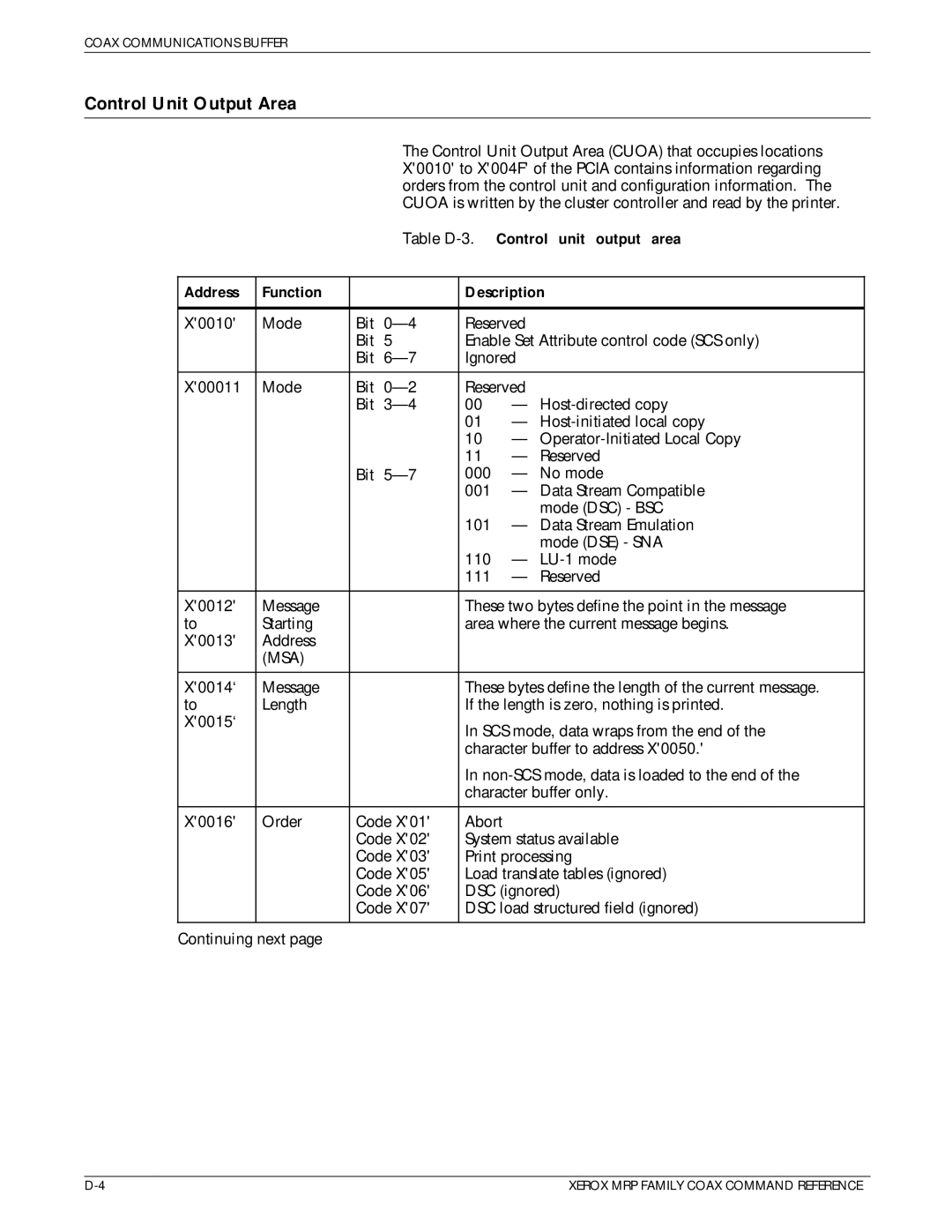
Control Unit Output Area
Control unit output area
SCS
Coax Communications Buffer
System Status Available SSA
Orders
Abort
Print order processing
DSC print order processing
Field Attribute FA character definitions Bit
Table D-5.Extended field attribute EFA Bit Value Description
Table D-6.Character attribute CA
Typeface Symbol Set Point
Table E-1.PCL fonts and equivalent IBM GFIDs Font name
IBM
EAN/UPC
Equivalent IBM GFIDs Font name
Dutch 601 Bold 1405
Table F-1.Recommended settings IBM printers
MRP Family Font Formats
FSL Y14 FSL Y37 FSL Y38
Printing a separator page between jobs
Sending data to multiple ports
Helpful Hints
Page
Query replies
Query Replies
CPI C6 MPP
DC MPP
0BÐ0E
Lcid = APL
0CÐ0D
Byte Value Hex Description
0AÐ0B
0EÐ0F
Table G-6.Highlight reply Byte Value Hex Description
0BÐ0C
Table G-8.Save restore Reply Byte Value Hex Description
Table G-9.Data chaining reply Byte Value Hex Description
Table G-10.Data streams reply
1AÐ1B
0DÐ0E
0C FF
1CÐ1D
International
Related publications
Xerox MRP Family publications
Publication Number Language
TCP/IP
IBM publications
Other publications
Rank Xerox documentation numbers
Rank Xerox documentaion Numbers Publication Language
VPS remote configuration
Overview of VPS
TRNCLASS=A,C,35
42XX/MRP transparency
Sepinfo = USEREX01 JES Sysout Selection Criteria
FCB Support = no Group Definitions Grpname = Usmg
PCL forms overview
SYSUT1 DD DSN = JK12345.FSLFILE.Y37,DISP = SHR
Using FormFixC to create macros
Installing FormFixC
· FORMFIXC.EXE · FORMFIXC.SYS · READMECX.DOC
Implementing FormFixC
Macro ID
SYSUT1 DD DSN = JK12345.PCLFILE.INVOICE,DISP = SHR
Transferring a macro to the IBM host
Sending a PCL macro to the printer
\COPY /B INVOICE.PCL LPT1
Overlay command
Merging variable data with a single form macro
Line
Call command
SYSUT1 DD DSN = JK12345.EBCDIC.VARDATA2,DISP = SHR
Line Line N
Merging variable data with different forms macros
Switching form orientation
Limitations
Space
Page
Glossary
BSC
COR
Cuoa
EAB
DOS
DSC
Ebcdic
EFA
GSM
HP PCL
LPL
Ipds
IRQ
LU1
GLOSSARY-8 Xerox MRP Family Coax Command Reference
PA1
OEM
OS/VS2
PA2
PDL
POA
RAM
SNA
ROM
SCS
SSA
Typeface
Troubleshooting
Throughput
Utility Pages
Index
Numerals
Index
Xerox MRP Family Coax Command Reference INDEX-3
INDEX-4 Xerox MRP Family Coax Command Reference
FSL, GLOSSARY-5
GDDM, 1-2, GLOSSARY-5
IRQ, 3-38, GLOSSARY-6
GLOSSARY-7
GLOSSARY-8
MSA + ML-1, D-9, GLOSSARY-8
LPL, 3-68, GLOSSARY-7
PCL 5, 1-1, 1-3, GLOSSARY-9 font, E-1 to E4t
Xerox MRP Family Coax Command Reference INDEX-9
INDEX-10 Xerox MRP Family Coax Command Reference
Valid
INDEX-12 Xerox MRP Family Coax Command Reference
Alternate Media Order Card
Business Reply Mail
T T E D