035-19046-002-B-0104

If the ICB senses voltage at the GV when not requested, the ICB will energize the draft motor. The ICB will not operate the furnace until voltage is no longer sensed at the GV. The draft motor is stopped when voltage is not sensed at the GV.

Any time the UCB senses voltage at the GV without a call for heat for a continuous five-minute period, the UCB will lock-on the indoor blower and a flash code is initiated (Table 28). When voltage is no longer sensed at the GV, the UCB will de- energize the indoor blower following the elapse of the fan off delay for heating.

If voltage has been sensed at the GV for at least 15 seconds during the fan on delay for heating and GV voltage or “W1” is lost, the indoor blower is forced on for the length of the fan off delay for heating.

During a call for heat, if the UCB does not sense voltage at the GV for a continuous five-minute period the UCB will ini- tiate a flash code (Table 28). The indoor blower motor will not be locked-on while there is no GV voltage.

However, if during a normal ignition sequence, the NPC has been tested to be open, IDM energized, NPC closes and then the first stage main valve (MV1) is detected as being on, the ignition sequence stops and the IDM is de-energized. (Since the NPC is wired serially with the main valve relays, de-ener- gizing the IDM will open the NPC). This failure is counted as a recycle and will result in an eventual recycle lockout. If the main valve continues to be energized after the IDM is de- energized the IDM is re-energized. The second stage (MV2) main valve is not monitored for closure after energization.

SAFETY CONTROLS

The UCB monitors the temperature limit switch of gas heat units.

The control circuit includes the following safety controls:

LIMIT SWITCH (LS)

This control is located inside the gas heat compartment and is set to open at the temperature indicated in the Gas Heat Limit Control Settings Table 24. It resets automatically. The limit switch operates when a high temperature condition, caused by inadequate supply air flow occurs, thus shutting down the heater and energizing the blower.

AUXILIARY LIMIT SWITCH (ALS)

This control is located inside the supply air compartment and is set to open at the temperature indicated in the Gas Heat Limit Control Settings Table 24. It resets manually. The limit switch operates when a high temperature condition, caused by inadequate supply air flow occurs, thus shutting down the heater and energizing the blower.

The auxiliary limit switch is wired in series with the limit switch. As such, the UCB cannot distinguish the auxiliary limit and the gas heat limit switch operation except the auxiliary is manual reset. Consequently, the control will respond in the same manner as outlined above under “Limit Switch”.

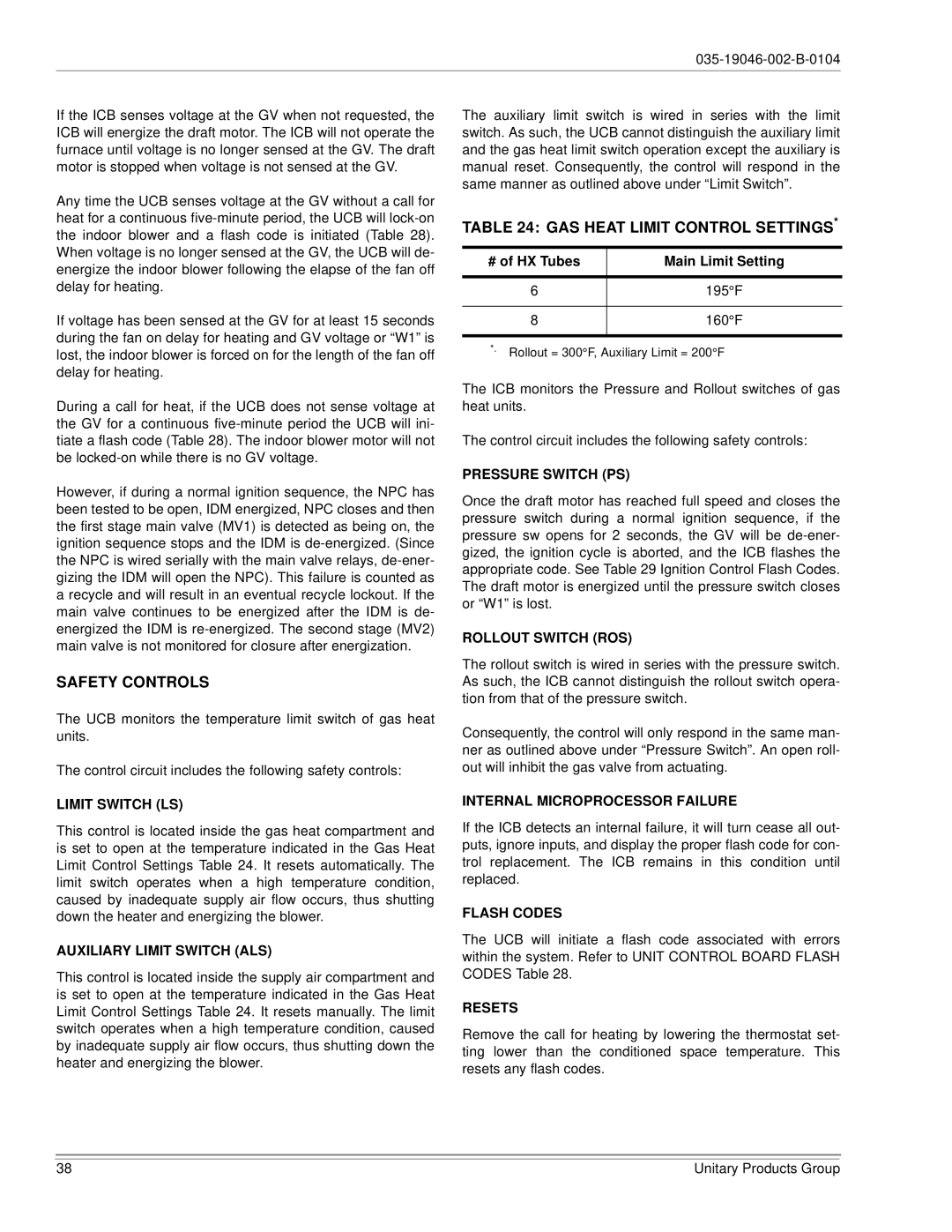
TABLE 24: GAS HEAT LIMIT CONTROL SETTINGS*

# of HX Tubes

Main Limit Setting


6

195°F


8

160°F


*. Rollout = 300°F, Auxiliary Limit = 200°F

The ICB monitors the Pressure and Rollout switches of gas heat units.

The control circuit includes the following safety controls:

PRESSURE SWITCH (PS)

Once the draft motor has reached full speed and closes the pressure switch during a normal ignition sequence, if the pressure sw opens for 2 seconds, the GV will be de-ener- gized, the ignition cycle is aborted, and the ICB flashes the appropriate code. See Table 29 Ignition Control Flash Codes. The draft motor is energized until the pressure switch closes or “W1” is lost.

ROLLOUT SWITCH (ROS)

The rollout switch is wired in series with the pressure switch. As such, the ICB cannot distinguish the rollout switch opera- tion from that of the pressure switch.

Consequently, the control will only respond in the same man- ner as outlined above under “Pressure Switch”. An open roll- out will inhibit the gas valve from actuating.

INTERNAL MICROPROCESSOR FAILURE

If the ICB detects an internal failure, it will turn cease all out- puts, ignore inputs, and display the proper flash code for con- trol replacement. The ICB remains in this condition until replaced.

FLASH CODES

The UCB will initiate a flash code associated with errors within the system. Refer to UNIT CONTROL BOARD FLASH CODES Table 28.

RESETS

Remove the call for heating by lowering the thermostat set- ting lower than the conditioned space temperature. This resets any flash codes.

38

Unitary Products Group

Page 38
Image 38
York DJ150 installation manual GAS Heat Limit Control Settings

DJ150 specifications

The York DJ150 is a standout model in the world of portable DJ equipment, designed to cater to both budding DJs and seasoned professionals. Its sleek and compact form factor makes it highly portable, allowing for easy transporting to gigs, parties, or personal events.

One of the main features of the DJ150 is its user-friendly interface, which includes a simplified control layout. This design boils down essential functions into accessible buttons and knobs, enabling DJs to focus on their mixes without distractions. The large jog wheels are not only responsive but also provide precision when scratching and cueing tracks, making it a joy to use for both live performances and practice sessions.

In terms of sound quality, the York DJ150 is equipped with high-performance audio circuitry. It ensures that sound clarity is maintained, with a dynamic range that captures the intricacies of music. The device supports multiple audio formats, offering versatility for DJs that work with various types of digital music files.

The DJ150 integrates advanced technologies that facilitate seamless mixing and creative expression. With features such as built-in sound effects, loops, and samples, DJs can add their personal touch to sets. Additionally, the model includes an intelligent beat matching function which automatically syncs the tempo of different tracks, allowing for smooth transitions and uninterrupted flow.

Connectivity is another strong point for the York DJ150. It offers multiple input and output options, including USB ports for quick connections to a laptop or external devices, line inputs for instruments or microphones, and headphones output for monitoring. This ensures that users can connect a wide range of equipment while maintaining a clean setup.

Durability plays a key role in the DJ150's design, as it is built to withstand the rigors of frequent use. Its robust construction and quality materials contribute to its longevity, appealing to those who value reliable gear.

In conclusion, the York DJ150 represents a versatile solution for DJs seeking a blend of portability, functionality, and sound quality. Its comprehensive features and professional-grade technologies position it as a strong contender in the DJ equipment market, making it suitable for performances of all levels. Whether you are a novice starting your DJ journey or a seasoned pro looking for an efficient tool, the DJ150 ticks all the boxes.