York GF9S*DH Section Vii Combustion Air And Vent System, UIM-B-0607, Single-WireStaging Operation

Models: GF9S*DH GY9S*DH GM9S*DH

1 40
Download 40 pages 62.69 Kb
Page 14
Image 14
Single-Wire Twinning Instructions

268890-UIM-B-0607

Single-Wire Twinning Instructions

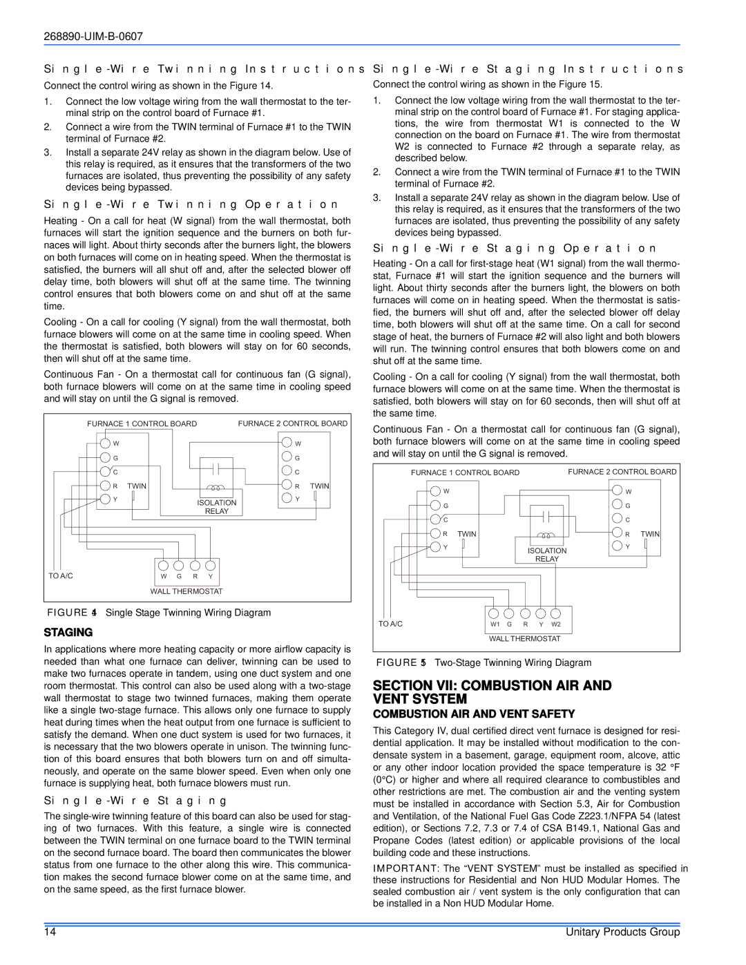
Connect the control wiring as shown in the Figure 14.

1.Connect the low voltage wiring from the wall thermostat to the ter- minal strip on the control board of Furnace #1.

2.Connect a wire from the TWIN terminal of Furnace #1 to the TWIN terminal of Furnace #2.

3.Install a separate 24V relay as shown in the diagram below. Use of this relay is required, as it ensures that the transformers of the two furnaces are isolated, thus preventing the possibility of any safety devices being bypassed.

Single-Wire Twinning Operation

Heating - On a call for heat (W signal) from the wall thermostat, both furnaces will start the ignition sequence and the burners on both fur- naces will light. About thirty seconds after the burners light, the blowers on both furnaces will come on in heating speed. When the thermostat is satisfied, the burners will all shut off and, after the selected blower off delay time, both blowers will shut off at the same time. The twinning control ensures that both blowers come on and shut off at the same time.

Cooling - On a call for cooling (Y signal) from the wall thermostat, both furnace blowers will come on at the same time in cooling speed. When the thermostat is satisfied, both blowers will stay on for 60 seconds, then will shut off at the same time.

Single-Wire Staging Instructions

Connect the control wiring as shown in the Figure 15.

1.Connect the low voltage wiring from the wall thermostat to the ter- minal strip on the control board of Furnace #1. For staging applica- tions, the wire from thermostat W1 is connected to the W connection on the board on Furnace #1. The wire from thermostat W2 is connected to Furnace #2 through a separate relay, as described below.

2.Connect a wire from the TWIN terminal of Furnace #1 to the TWIN terminal of Furnace #2.

3.Install a separate 24V relay as shown in the diagram below. Use of this relay is required, as it ensures that the transformers of the two furnaces are isolated, thus preventing the possibility of any safety devices being bypassed.

Single-Wire Staging Operation

Heating - On a call for first-stage heat (W1 signal) from the wall thermo- stat, Furnace #1 will start the ignition sequence and the burners will light. About thirty seconds after the burners light, the blowers on both furnaces will come on in heating speed. When the thermostat is satis- fied, the burners will shut off and, after the selected blower off delay time, both blowers will shut off at the same time. On a call for second stage of heat, the burners of Furnace #2 will also light and both blowers will run. The twinning control ensures that both blowers come on and shut off at the same time.

Continuous Fan - On a thermostat call for continuous fan (G signal), both furnace blowers will come on at the same time in cooling speed and will stay on until the G signal is removed.

FURNACE 1 CONTROL BOARD


FURNACE 2 CONTROL BOARD

W


W


G


G


C


C


R

TWIN


R

TWIN

Y


ISOLATION

Y


RELAY


TO A/C

W

G

R

Y


WALL THERMOSTAT


FIGURE 14: Single Stage Twinning Wiring Diagram

STAGING

In applications where more heating capacity or more airflow capacity is needed than what one furnace can deliver, twinning can be used to make two furnaces operate in tandem, using one duct system and one room thermostat. This control can also be used along with a two-stage wall thermostat to stage two twinned furnaces, making them operate like a single two-stage furnace. This allows only one furnace to supply heat during times when the heat output from one furnace is sufficient to satisfy the demand. When one duct system is used for two furnaces, it is necessary that the two blowers operate in unison. The twinning func- tion of this board ensures that both blowers turn on and off simulta- neously, and operate on the same blower speed. Even when only one furnace is supplying heat, both furnace blowers must run.

Single-Wire Staging

The single-wire twinning feature of this board can also be used for stag- ing of two furnaces. With this feature, a single wire is connected between the TWIN terminal on one furnace board to the TWIN terminal on the second furnace board. The board then communicates the blower status from one furnace to the other along this wire. This communica- tion makes the second furnace blower come on at the same time, and on the same speed, as the first furnace blower.

Cooling - On a call for cooling (Y signal) from the wall thermostat, both furnace blowers will come on at the same time. When the thermostat is satisfied, both blowers will stay on for 60 seconds, then will shut off at the same time.

Continuous Fan - On a thermostat call for continuous fan (G signal), both furnace blowers will come on at the same time in cooling speed and will stay on until the G signal is removed.

FURNACE 1 CONTROL BOARD


FURNACE 2 CONTROL BOARD

W


W


G


G


C


C


R

TWIN


R

TWIN

Y


ISOLATION

Y


RELAY


TO A/C

W1 G

R

Y

W2


WALL THERMOSTAT


FIGURE 15: Two-Stage Twinning Wiring Diagram

SECTION VII: COMBUSTION AIR AND VENT SYSTEM

COMBUSTION AIR AND VENT SAFETY

This Category IV, dual certified direct vent furnace is designed for resi- dential application. It may be installed without modification to the con- densate system in a basement, garage, equipment room, alcove, attic or any other indoor location provided the space temperature is 32 °F (0°C) or higher and where all required clearance to combustibles and other restrictions are met. The combustion air and the venting system must be installed in accordance with Section 5.3, Air for Combustion and Ventilation, of the National Fuel Gas Code Z223.1/NFPA 54 (latest edition), or Sections 7.2, 7.3 or 7.4 of CSA B149.1, National Gas and Propane Codes (latest edition) or applicable provisions of the local building code and these instructions.

IMPORTANT: The “VENT SYSTEM” must be installed as specified in these instructions for Residential and Non HUD Modular Homes. The sealed combustion air / vent system is the only configuration that can be installed in a Non HUD Modular Home.

14

Unitary Products Group

Page 14
Image 14
York GF9S*DH, GM9S*DH Section Vii Combustion Air And Vent System, UIM-B-0607, Single-WireTwinning Instructions, Staging