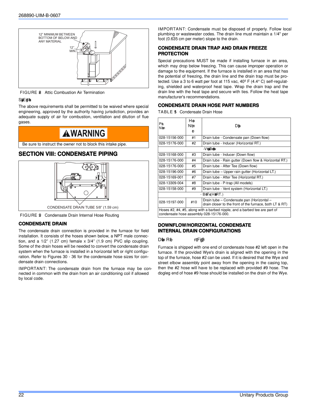
GF9S*DH, GY9S*DH, GM9S*DH specifications
The York GM9S*DH, GF9S*DH, and GY9S*DH series air conditioning systems are known for their robust performance, reliability, and energy efficiency. These models are well-suited for both residential and light commercial applications, making them versatile options for a range of users.One of the standout features of these systems is their high efficiency. The GM9S*DH is equipped with advanced heating and cooling technologies that allow it to achieve excellent SEER (Seasonal Energy Efficiency Ratio) ratings. This translates to lower energy consumption and reduced utility bills for homeowners and business operators alike. The GF9S*DH model further enhances this efficiency by incorporating variable-speed blowers that adjust airflow based on specific needs, ensuring that the system operates only as necessary.
Reliability is another key characteristic of the York GM9S*DH, GF9S*DH, and GY9S*DH series. These models are engineered with durable components and rigorous performance testing, which contributes to their long lifespan and minimizes the need for repairs. Moreover, they come with robust warranties that provide peace of mind for consumers.
In terms of technology, these units utilize a smart thermostat feature that allows for precise temperature control and programmable settings. This feature not only enhances comfort but also contributes to energy savings by allowing users to set optimal cooling or heating schedules. The systems are also designed with quiet operation in mind, employing sound-dampening features that minimize noise levels, which is particularly beneficial for residential installations.
The installation of the York GM9S*DH, GF9S*DH, and GY9S*DH systems is straightforward, offering flexibility in placement and integration with various home or office setups. Their compact design allows them to fit seamlessly into different environments without compromising on performance.
Additionally, the systems are equipped with advanced filtration options that improve indoor air quality by capturing allergens and pollutants. This is particularly beneficial for families with children or members who suffer from allergies.
Overall, the York GM9S*DH, GF9S*DH, and GY9S*DH series provide exceptional performance, energy efficiency, and reliability, making them an ideal choice for maintaining a comfortable indoor environment. With their cutting-edge technologies and user-friendly features, these systems represent an excellent investment for anyone looking to enhance their heating and cooling experience.

