Downflow Air Conditioning Coil Cabinet
The Cooling Coil Cabinet can be used in place of the combustible floor base for downflow installations on combustible materials. The furnace should be installed with the cooling coil cabinet specifically intended for downflow applications. The cooling coil cabinet must be secured to the floor. A supply air duct plenum is installed through the opening pro- vided. The supply air duct is then secured to the duct system with screws and sealed to prevent leaks. If a matching cooling coil is used, it may be placed directly on the furnace outlet using the accessory transi- tion kit and sealed to prevent leakage. The transition kit must be used to secure the cooling coil cabinet to the furnace casing when installed in a downflow configuration.
These kits are required in downflow application when using G*F* series coils. These kits are not required with MC/FC series coils, but please ensurethat the coil and furnace are sucured and that there are noair leaks.
This transition kit may be installed in one of two ways. The transition kit may be installed and secured to either the furnace or the cooling coil cabinet by the use of screws and then it must be sealed to prevent leaks.
•If the transition kit has been installed on the cooling coil cabinet it must be secured to the cooling coil cabinet with screws. The sup- ply air side of the furnace is then placed on the cooling coil cabi- net and then sealed for leaks.
•If the transition kit has been installed on the supply air side of the furnace it must be secured to the furnace with screws. The fur- nace and the transition kit are then placed on the cooling coil cab- inet and then sealed for leaks.
NOTE: Refer to instructions packed out with coil cabinet, for securing and sealing to the furnace.
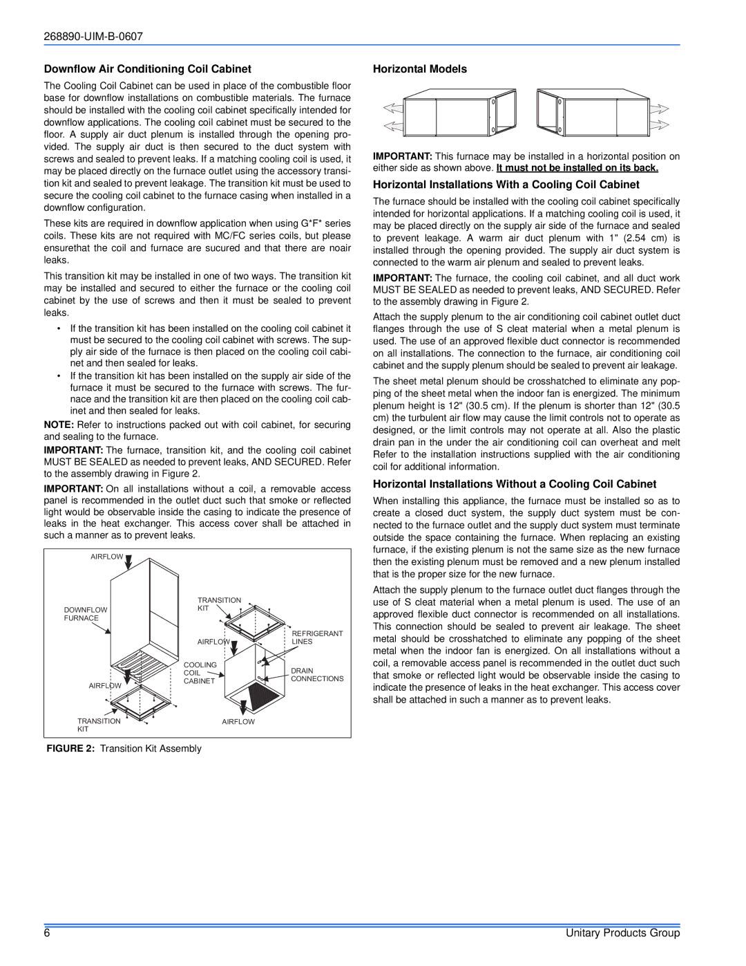
IMPORTANT: The furnace, transition kit, and the cooling coil cabinet MUST BE SEALED as needed to prevent leaks, AND SECURED. Refer to the assembly drawing in Figure 2.
IMPORTANT: On all installations without a coil, a removable access panel is recommended in the outlet duct such that smoke or reflected light would be observable inside the casing to indicate the presence of leaks in the heat exchanger. This access cover shall be attached in such a manner as to prevent leaks.
AIRFLOW 
| TRANSITION | |
DOWNFLOW | KIT | |
| |
FURNACE | | |
| | REFRIGERANT |
| AIRFLOW | LINES |
| COOLING | DRAIN |
| COIL |
| CONNECTIONS |
| CABINET |
AIRFLOW | |
| |
TRANSITION | AIRFLOW | |
KIT | | |
Horizontal Models
IMPORTANT: This furnace may be installed in a horizontal position on either side as shown above. It must not be installed on its back.
Horizontal Installations With a Cooling Coil Cabinet
The furnace should be installed with the cooling coil cabinet specifically intended for horizontal applications. If a matching cooling coil is used, it may be placed directly on the supply air side of the furnace and sealed to prevent leakage. A warm air duct plenum with 1" (2.54 cm) is installed through the opening provided. The supply air duct system is connected to the warm air plenum and sealed to prevent leaks.
IMPORTANT: The furnace, the cooling coil cabinet, and all duct work MUST BE SEALED as needed to prevent leaks, AND SECURED. Refer to the assembly drawing in Figure 2.
Attach the supply plenum to the air conditioning coil cabinet outlet duct flanges through the use of S cleat material when a metal plenum is used. The use of an approved flexible duct connector is recommended on all installations. The connection to the furnace, air conditioning coil cabinet and the supply plenum should be sealed to prevent air leakage.
The sheet metal plenum should be crosshatched to eliminate any pop- ping of the sheet metal when the indoor fan is energized. The minimum plenum height is 12" (30.5 cm). If the plenum is shorter than 12" (30.5 cm) the turbulent air flow may cause the limit controls not to operate as designed, or the limit controls may not operate at all. Also the plastic drain pan in the under the air conditioning coil can overheat and melt Refer to the installation instructions supplied with the air conditioning coil for additional information.
Horizontal Installations Without a Cooling Coil Cabinet
When installing this appliance, the furnace must be installed so as to create a closed duct system, the supply duct system must be con- nected to the furnace outlet and the supply duct system must terminate outside the space containing the furnace. When replacing an existing furnace, if the existing plenum is not the same size as the new furnace then the existing plenum must be removed and a new plenum installed that is the proper size for the new furnace.
Attach the supply plenum to the furnace outlet duct flanges through the use of S cleat material when a metal plenum is used. The use of an approved flexible duct connector is recommended on all installations. This connection should be sealed to prevent air leakage. The sheet metal should be crosshatched to eliminate any popping of the sheet metal when the indoor fan is energized. On all installations without a coil, a removable access panel is recommended in the outlet duct such that smoke or reflected light would be observable inside the casing to indicate the presence of leaks in the heat exchanger. This access cover shall be attached in such a manner as to prevent leaks.