Downflow/Horizontal furnaces for installation on combustible floor- ing only when installed on the accessory combustible floor base on wood flooring only and shall not be installed directly on carpeting, tile or other combustible material.
Check the rating plate and power supply to be sure that the electri- cal characteristics match. All models use nominal 115 VAC, 1 Phase 60Hz power supply.
Furnace shall be installed so the electrical components are pro- tected from water.
Installation in a residential garage:
1.A gas-fired furnace for installation in a residential garage must be installed so the burner(s) and the ignition source are located not less than 18 inches (46 cm) above the floor, and the furnace must be located or protected to avoid physical damage by vehicles.
TABLE 1: Unit Clearances to Combustibles
Application | | Downflow | Horizontal |
Top | In. (cm) | 1 (2.5) | 0 (0) |
Front | In. (cm) | 3 (7.6) | 3 (7.6) |
Rear | In. (cm) | 0 (0) | 0 (0) |
Left Side | In. (cm) | 0 (0) | 1 (2.5) |
Right Side | In. (cm) | 0 (0) | 1 (2.5) |
Flue | In. (cm) | 0 (0) | 0 (0) |
Floor / Bottom | In. (cm) | 1 (2.5)1 | 0 (0) |
Closet | | Yes | Yes |
Alcove | | Yes | Yes |
Attic | | Yes | Yes |
Line Contact | | NA | Yes2 |
1.Combustible floor base or air conditioning coil required for use on combusti- ble floor.
2.Line contact only permitted between lines formed by the intersection of the rear panel (top in horizontal position) of the furnace jacket and building joists, studs or framing.
SECTION II: DUCTWORK
DUCTWORK GENERAL INFORMATION
The duct system’s design and installation must:
1.Handle an air volume appropriate for the served space and within the operating parameters of the furnace specifications.
2.Be installed in accordance with standards of NFPA (National Fire Protection Association) as outlined in NFPA pamphlets 90A and 90B (latest editions) or applicable national, provincial, or state, and local fire and safety codes.
3.Create a closed duct system. For residential and Non-HUD Modu- lar Home installations, when a furnace is installed so that the sup- ply ducts carry air circulated by the furnace to areas outside the space containing the furnace, the return air shall also be handled by a duct(s) sealed to the furnace casing and terminating outside the space containing the furnace.
4.Complete a path for heated or cooled air to circulate through the air conditioning and heating equipment and to and from the condi- tioned space.
The cooling coil must be installed in the supply air duct, down- stream of the furnace. Cooled air may not be passed over the heat exchanger.
When the furnace is used in conjunction with a cooling coil, the coil must be installed parallel with, or in the supply air side of the furnace to avoid condensation in the primary heat exchanger. When a parallel flow arrangement is used, dampers or other means used to control airflow must be adequate to prevent chilled air from entering the furnace. If manually operated, the damper must be equipped with means to pre- vent the furnace or the air conditioner from operating unless the damper is in full heat or cool position.
The duct system must be properly sized to obtain the correct airflow for the furnace size that is being installed.
Refer to Table 7 and the furnace rating plate for the correct rise range and static pressures
If the ducts are undersized, the result will be high duct static pres- sures and/or high temperature rises which can result in a heat exchanger OVERHEATING CONDITION. This condition can result in premature heat exchanger failure, which can result in personal injury, property damage, or death.
FLOOR BASE AND DUCTWORK INSTALLATION
Downflow Combustible Floor Base
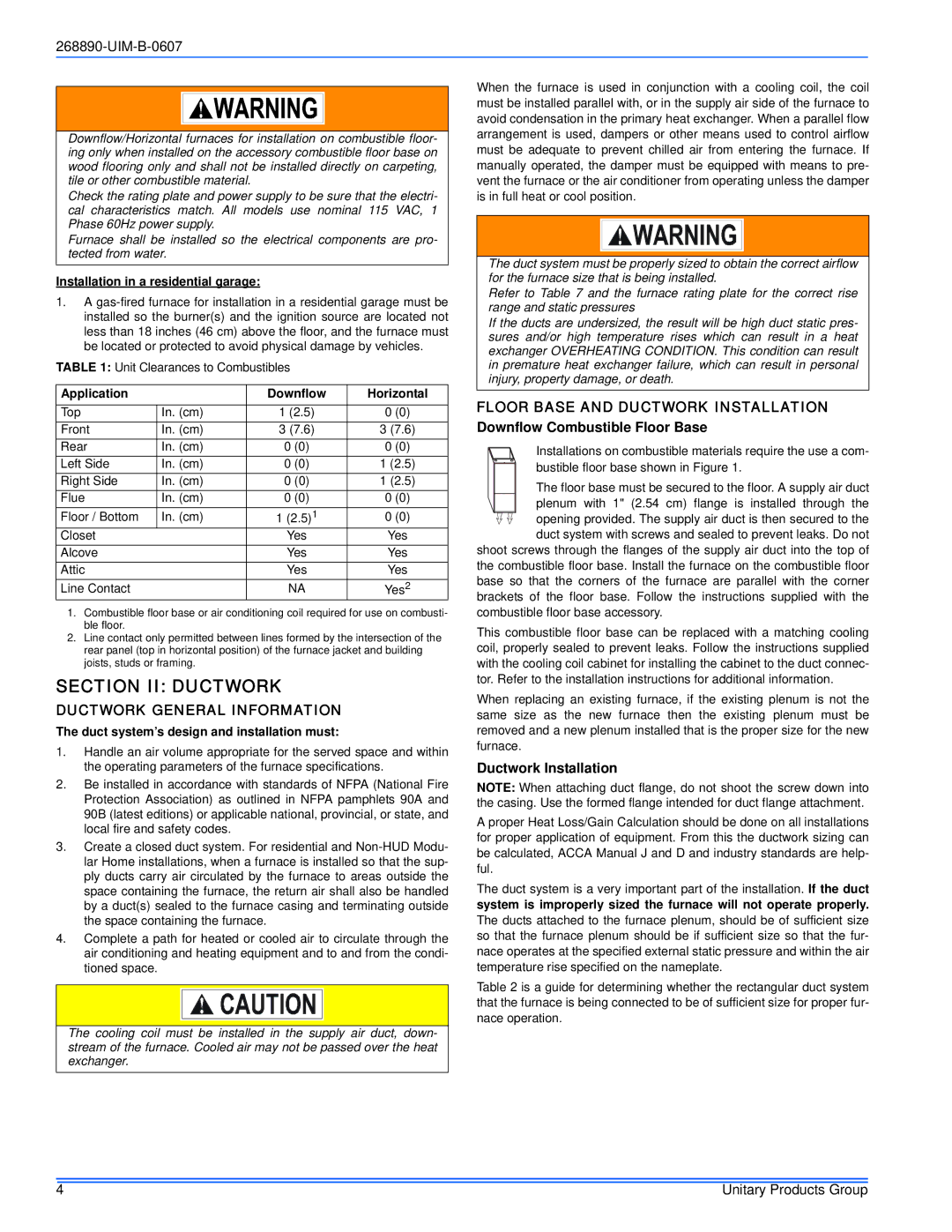
Installations on combustible materials require the use a com- bustible floor base shown in Figure 1.
The floor base must be secured to the floor. A supply air duct plenum with 1" (2.54 cm) flange is installed through the opening provided. The supply air duct is then secured to the duct system with screws and sealed to prevent leaks. Do not
shoot screws through the flanges of the supply air duct into the top of the combustible floor base. Install the furnace on the combustible floor base so that the corners of the furnace are parallel with the corner brackets of the floor base. Follow the instructions supplied with the combustible floor base accessory.
This combustible floor base can be replaced with a matching cooling coil, properly sealed to prevent leaks. Follow the instructions supplied with the cooling coil cabinet for installing the cabinet to the duct connec- tor. Refer to the installation instructions for additional information.
When replacing an existing furnace, if the existing plenum is not the same size as the new furnace then the existing plenum must be removed and a new plenum installed that is the proper size for the new furnace.
Ductwork Installation
NOTE: When attaching duct flange, do not shoot the screw down into the casing. Use the formed flange intended for duct flange attachment.
A proper Heat Loss/Gain Calculation should be done on all installations for proper application of equipment. From this the ductwork sizing can be calculated, ACCA Manual J and D and industry standards are help- ful.
The duct system is a very important part of the installation. If the duct system is improperly sized the furnace will not operate properly. The ducts attached to the furnace plenum, should be of sufficient size so that the furnace plenum should be if sufficient size so that the fur- nace operates at the specified external static pressure and within the air temperature rise specified on the nameplate.
Table 2 is a guide for determining whether the rectangular duct system that the furnace is being connected to be of sufficient size for proper fur- nace operation.