268890-UIM-B-0607

Be sure to relight any gas appliances that were turned off at the start of this input check.

TABLE 16: Inlet Gas Pressure Range

INLET GAS PRESSURE RANGE


Natural Gas

Propane (LP)

Minimum

4.5” W.C. (1.12 kPa)

8.0” W.C. (1.99 kPa)


Maximum

10.5” W.C. (2.61 kPa)

13.0” (3.24 kPa) W.C.


IMPORTANT: The inlet gas pressure operating range table specifies what the minimum and maximum gas line presures must be for the fur- nace to operate safely. The gas line pressure MUST BE

7” W.C. (1.74 kPA) for Natural Gas

11” W.C. (2.74 kPA) for Propane (LP) Gas

in order to obtain the BTU input specified on the rating plate and/or the

Reading the gas pressure with the burner box cover removed - Remove the screws securing the burner box front cover plate. Remove the cover. The gasket and may stick in place. Connect the positive side of the manometer to the gas valve as described in E above. There will be no second connection to the manometer, as it will reference atmo- spheric pressure. Refer to Figure 39 for connection details.

IMPORTANT: The cap for the pressure regulator must be removed entirely to gain access to the adjustment screw. Loosening or tightening the cap does not adjust the flow of gas.

1.Refer to Figure 38 for location of pressure regulator adjustment cap and adjustment screw on main gas valve.

2.Turn gas and electrical supplies on and follow the operating instructions to place the unit back in operation.

3.Adjust manifold pressure by adjusting gas valve regulator screw for the appropriate gas per the following:

TABLE 17: Nominal Manifold Pressure

NOMINAL MANIFOLD PRESSURE

nominal manifold pressure specified in these instructions and on the rating plate.

ADJUSTMENT OF MANIFOLD GAS PRESSURE

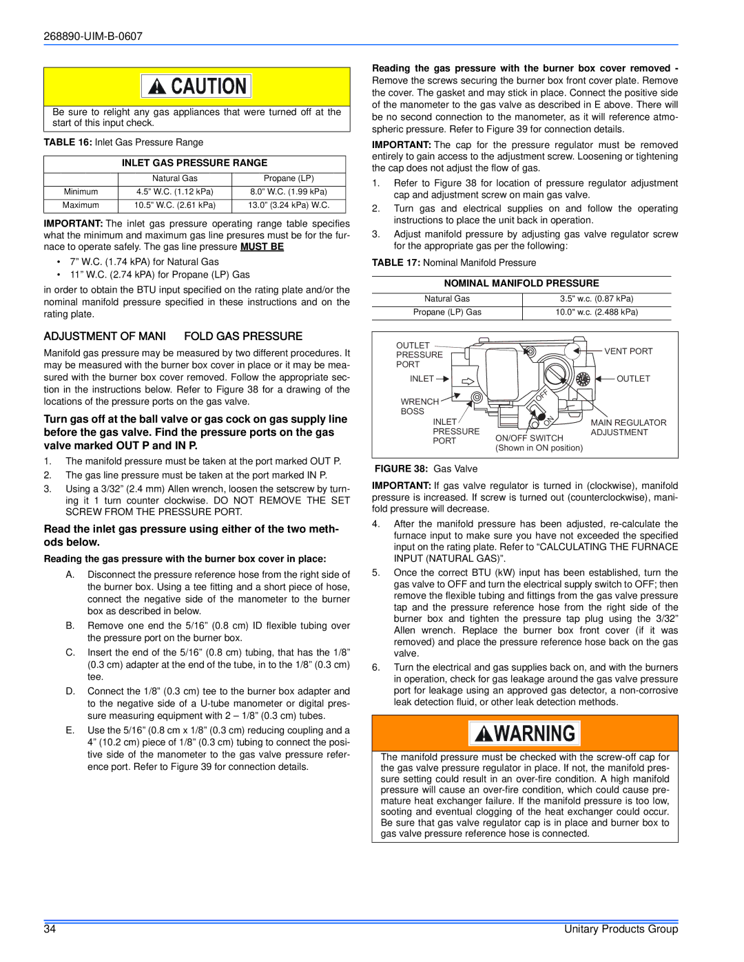
Manifold gas pressure may be measured by two different procedures. It may be measured with the burner box cover in place or it may be mea- sured with the burner box cover removed. Follow the appropriate sec- tion in the instructions below. Refer to Figure 38 for a drawing of the locations of the pressure ports on the gas valve.

Turn gas off at the ball valve or gas cock on gas supply line before the gas valve. Find the pressure ports on the gas valve marked OUT P and IN P.

Natural Gas

Propane (LP) Gas

OUTLET

PRESSURE

PORT

INLET

WRENCH BOSS

INLET PRESSURE PORT


3.5" w.c. (0.87 kPa)


10.0" w.c. (2.488 kPa)


VENT PORT


OUTLET

OFF


ON

MAIN REGULATOR


ADJUSTMENT

ON/OFF SWITCH

(Shown in ON position)

1.The manifold pressure must be taken at the port marked OUT P.

2.The gas line pressure must be taken at the port marked IN P.

3.Using a 3/32” (2.4 mm) Allen wrench, loosen the setscrew by turn- ing it 1 turn counter clockwise. DO NOT REMOVE THE SET SCREW FROM THE PRESSURE PORT.

Read the inlet gas pressure using either of the two meth- ods below.

Reading the gas pressure with the burner box cover in place:

A.Disconnect the pressure reference hose from the right side of the burner box. Using a tee fitting and a short piece of hose, connect the negative side of the manometer to the burner box as described in below.

B.Remove one end the 5/16” (0.8 cm) ID flexible tubing over the pressure port on the burner box.

C.Insert the end of the 5/16” (0.8 cm) tubing, that has the 1/8” (0.3 cm) adapter at the end of the tube, in to the 1/8” (0.3 cm) tee.

D.Connect the 1/8” (0.3 cm) tee to the burner box adapter and to the negative side of a U-tube manometer or digital pres- sure measuring equipment with 2 – 1/8” (0.3 cm) tubes.

E.Use the 5/16” (0.8 cm x 1/8” (0.3 cm) reducing coupling and a 4” (10.2 cm) piece of 1/8” (0.3 cm) tubing to connect the posi- tive side of the manometer to the gas valve pressure refer- ence port. Refer to Figure 39 for connection details.

FIGURE 38: Gas Valve

IMPORTANT: If gas valve regulator is turned in (clockwise), manifold pressure is increased. If screw is turned out (counterclockwise), mani- fold pressure will decrease.

4.After the manifold pressure has been adjusted, re-calculate the furnace input to make sure you have not exceeded the specified input on the rating plate. Refer to “CALCULATING THE FURNACE INPUT (NATURAL GAS)”.

5.Once the correct BTU (kW) input has been established, turn the gas valve to OFF and turn the electrical supply switch to OFF; then remove the flexible tubing and fittings from the gas valve pressure tap and the pressure reference hose from the right side of the burner box and tighten the pressure tap plug using the 3/32” Allen wrench. Replace the burner box front cover (if it was removed) and place the pressure reference hose back on the gas valve.

6.Turn the electrical and gas supplies back on, and with the burners in operation, check for gas leakage around the gas valve pressure port for leakage using an approved gas detector, a non-corrosive leak detection fluid, or other leak detection methods.

The manifold pressure must be checked with the screw-off cap for the gas valve pressure regulator in place. If not, the manifold pres- sure setting could result in an over-fire condition. A high manifold pressure will cause an over-fire condition, which could cause pre- mature heat exchanger failure. If the manifold pressure is too low, sooting and eventual clogging of the heat exchanger could occur. Be sure that gas valve regulator cap is in place and burner box to gas valve pressure reference hose is connected.

34

Unitary Products Group

Page 34
Image 34
York GY9S*DH, GM9S*DH, GF9S*DH Adjustment of Manifold GAS Pressure, Inlet GAS Pressure Range, Nominal Manifold Pressure

GF9S*DH, GY9S*DH, GM9S*DH specifications

The York GM9S*DH, GF9S*DH, and GY9S*DH series air conditioning systems are known for their robust performance, reliability, and energy efficiency. These models are well-suited for both residential and light commercial applications, making them versatile options for a range of users.

One of the standout features of these systems is their high efficiency. The GM9S*DH is equipped with advanced heating and cooling technologies that allow it to achieve excellent SEER (Seasonal Energy Efficiency Ratio) ratings. This translates to lower energy consumption and reduced utility bills for homeowners and business operators alike. The GF9S*DH model further enhances this efficiency by incorporating variable-speed blowers that adjust airflow based on specific needs, ensuring that the system operates only as necessary.

Reliability is another key characteristic of the York GM9S*DH, GF9S*DH, and GY9S*DH series. These models are engineered with durable components and rigorous performance testing, which contributes to their long lifespan and minimizes the need for repairs. Moreover, they come with robust warranties that provide peace of mind for consumers.

In terms of technology, these units utilize a smart thermostat feature that allows for precise temperature control and programmable settings. This feature not only enhances comfort but also contributes to energy savings by allowing users to set optimal cooling or heating schedules. The systems are also designed with quiet operation in mind, employing sound-dampening features that minimize noise levels, which is particularly beneficial for residential installations.

The installation of the York GM9S*DH, GF9S*DH, and GY9S*DH systems is straightforward, offering flexibility in placement and integration with various home or office setups. Their compact design allows them to fit seamlessly into different environments without compromising on performance.

Additionally, the systems are equipped with advanced filtration options that improve indoor air quality by capturing allergens and pollutants. This is particularly beneficial for families with children or members who suffer from allergies.

Overall, the York GM9S*DH, GF9S*DH, and GY9S*DH series provide exceptional performance, energy efficiency, and reliability, making them an ideal choice for maintaining a comfortable indoor environment. With their cutting-edge technologies and user-friendly features, these systems represent an excellent investment for anyone looking to enhance their heating and cooling experience.