York GF9S*DH UIM-B-0607, Unitary Products Group, Input, Return1, Rectangular2, Round2, Supply3

Models: GF9S*DH GY9S*DH GM9S*DH

1 40
Download 40 pages 62.69 Kb
Page 5
Image 5
Input

268890-UIM-B-0607

Use the Example below to help you in calculating the duct area to deter- mine whether the ducts have sufficient area so that the furnace oper- ates at the specified external static pressure and within the air temperature rise specified on the nameplate.

The following are general duct sizing guidelines that may not serve to requirements of every application.

Example: The furnace input is 80,000 BTUH, 1,200 CFM blower requirement. The recommended duct area is 216 sq.in, there are two 8 x 12 rectangular ducts attached to the plenum and there are two 7 inch round ducts attached to the furnace.

1.Take 8 x 12, which equals 96 square inch x 2 = 192 square inches then go to round duct size located in Table 3.

2.The square inch area for 7 inch round ducts, 38.4 square inch x 2 = 76.8 square inches,

3.Then take the 192 square inch from the rectangular duct and add it to the 76.8 square inch of round duct. The total square inch of duct attached to the furnace supply plenum is 268.8 square inches. This exceeds the recommended 216 square inch of duct.

In this example, the duct system attached to the plenum has a sufficient area so that the furnace operates at the specified external static pres- sure and within the air temperature rise specified on the nameplate. Providing the return duct is properly sized as well.

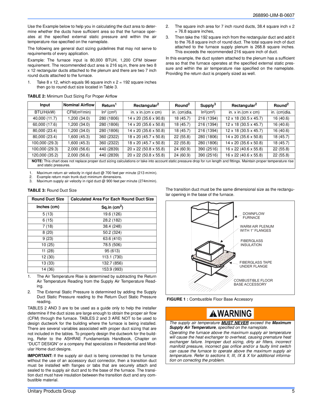
TABLE 2: Minimum Duct Sizing For Proper Airflow

Input

Nominal Airflow

Return1

Rectangular2

Round2

Supply3

Rectangular2

Round2

BTU/H(kW)

CFM(m³/min)

In² (cm²)

in. x in.(cm x cm)

in. (cm)dia.

In²(cm²)

in. x in.(cm x cm)

in. (cm)dia.

40,000 (11.7)

1,200 (34.0)

280 (1806)

14 x 20 (35.6 x 90.8)

18 (45.7)

216 (1394)

12 x 18 (30.5 x 45.7)

16 (40.6)

60,000 (17.6)

1,200 (34.0)

280 (1806)

14 x 20 (35.6 x 50.8)

18 (45.7)

216 (1394)

12 x 18 (30.5 x 45.7)

16 (40.6)

80,000 (23.4)

1,200 (34.0)

280 (1806)

14 x 20 (35.6 x 50.8)

18 (45.7)

216 (1394)

12 x 18 (30.5 x 45.7)

16 (40.6)

80,000 (23.4)

1,600 (45.3)

360 (2322)

18 x 20 (45.7 x 50.8)

22 (55.8)

280 (1806)

14 x 20 (35.6 x 50.8)

18 (45.7)

100,000 (29.3)

1,600 (45.3)

360 (2322)

18 x 20 (45.7 x 50.8)

22 (55.8)

280 (1806)

14 x 20 (35.6 x 50.8)

18 (45.7)

100,000 (29.3)

2,000 (56.6)

440 (2839)

20 x 22 (50.8 x 55.8)

24 (60.9)

390 (2516)

16 x 22 (40.6 x 55.8)

22 (55.8)

120,000 (35.2)

2,000 (56.6)

440 (2839)

20 x 22 (50.8 x 55.8)

24 (60.9)

390 (2516)

16 x 22 (40.6 x 55.8)

22 (55.8)

NOTE: This chart does not replace proper duct sizing calculations or take into account static pressure drop for run length and fittings. Maintain proper temperature rise and static pressures.

1.Maximum return air velocity in rigid duct @ 700 feet per minute (213 m/min).

2.Example return main trunk duct minimum dimensions.

3.Maximum supply air velocity in rigid duct @ 900 feet per minute (274m/min).

TABLE 3: Round Duct Size

Round Duct Size

Calculated Area For Each Round Duct Size


Inches (cm)

Sq.in (cm2)

5 (13)

19.6 (126)

6 (15)

28.2 (182)

7 (18)

38.4 (248)

8 (20)

50.2 (324)

9 (23)

63.6 (410)

10 (25)

78.5 (506)

11 (28)

95 (613)

12 (30)

113.1 (730)

13 (33)

132.7 (856)

14 (36)

153.9 (993)

1.The Air Temperature Rise is determined by subtracting the Return Air Temperature Reading from the Supply Air Temperature Read- ing.

2.The External Static Pressure is determined by adding the Supply Duct Static Pressure reading to the Return Duct Static Pressure reading.

TABLES 2 AND 3 are to be used as a guide only to help the installer determine if the duct sizes are large enough to obtain the proper air flow (CFM) through the furnace. TABLES 2 and 3 ARE NOT to be used to design ductwork for the building where the furnace is being installed. There are several variables associated with proper duct sizing that are not included in the tables. To properly design the ductwork for the build- ing, Refer to the ASHRAE Fundamentals Handbook, Chapter on “DUCT DESIGN” or a company that specializes in Residential and Mod- ular Home duct designs.

IMPORTANT: If the supply air duct is being connected to the furnace without the use of an accessory duct connector, then a transition duct must be installed with flanges or tabs that are securely attach and sealed to the supply air duct and to the base of the furnace. The transi- tion duct must have insulation between the transition duct and any com- bustible material.

The transition duct must be the same dimensional size as the rectangu- lar opening in the base of the furnace.

DOWNFLOW

FURNACE

WARM AIR PLENUM

WITH 1” FLANGES

FIBERGLASS

INSULATION

FIBERGLASS TAPE

UNDER FLANGE

COMBUSTIBLE FLOOR

BASE ACCESSORY

FIGURE 1 : Combustible Floor Base Accessory

The supply air temperature MUST NEVER exceed the Maximum Supply Air Temperature, specified on the nameplate.

Operating the furnace above the maximum supply air temperature will cause the heat exchanger to overheat, causing premature heat exchanger failure. Improper duct sizing, dirty air filters, incorrect manifold pressure, incorrect gas orifice and/or a faulty limit switch can cause the furnace to operate above the maximum supply air temperature. Refer to sections II, III, IX & X for additional informa- tion on correcting the problem.

Unitary Products Group

5

Page 5
Image 5
York GF9S*DH, GM9S*DH UIM-B-0607, Unitary Products Group, Input, Return1, Rectangular2, Round2, Supply3, Round Duct Size