FORM
Application Data (continued)
In addition, the ASHRAE Standard 15 requires a refriger- ant vapor detector to be employed for all refrigerants. It is to be located in area where refrigerant from a leak would be likely to concentrate. An alarm is to be activated and the mechanical ventilation started at a value no greater than the TLV (Threshold Limit Value) of the refrigerant.
ELECTRICAL CONSIDERATIONS
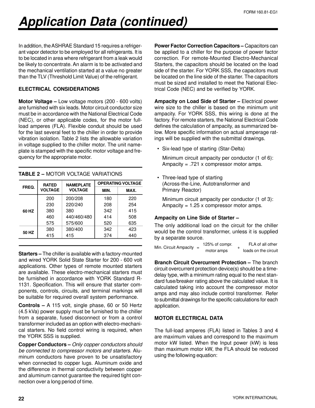
Motor Voltage – Low voltage motors (200 - 600 volts) are furnished with six leads. Motor circuit conductor size must be in accordance with the National Electrical Code (NEC), or other applicable codes, for the motor full- load amperes (FLA). Flexible conduit should be used for the last several feet to the chiller in order to provide vibration isolation. Table 2 lists the allowable variation in voltage supplied to the chiller motor. The unit name- plate is stamped with the specific motor voltage and fre- quency for the appropriate motor.
TABLE 2 – MOTOR VOLTAGE VARIATIONS
| FREQ. | RATED | NAMEPLATE | OPERATING VOLTAGE |
| |
| VOLTAGE | VOLTAGE | MIN. | MAX. |
| |
|
|
| ||||
|
|
|
|
|
|
|
|
| 200 | 200/208 | 180 | 220 |
|
|
| 230 | 220/240 | 208 | 254 |
|
| 60 HZ | 380 | 380 | 342 | 415 |
|
|
| 460 | 440/460/480 | 414 | 508 |
|
|
| 575 | 575/600 | 520 | 635 |
|
| 50 HZ | 380 | 380/400 | 342 | 423 |
|
| 415 | 415 | 374 | 440 |
| |
|
|
| ||||
|
|
|
|
|
|
|
Starters – The chiller is available with a
Controls – A 115 volt, single phase, 60 or 50 Hertz (4.5 kVa) power supply must be furnished to the chiller from a separate, fused disconnect or from a control transformer included as an option with
Copper Conductors – Only copper conductors should be connected to compressor motors and starters. Alu- minum conductors have proven to be unsatisfactory when connected to copper lugs. Aluminum oxide and the difference in thermal conductivity between copper and aluminum cannot guarantee the required tight con- nection over a long period of time.
Power Factor Correction Capacitors – Capacitors can be applied to a chiller for the purpose of power factor correction. For
Ampacity on Load Side of Starter – Electrical power wire size to the chiller is based on the minimum unit ampacity. For YORK SSS, this wiring is done at the factory. For remote starters, the National Electrical Code defines the calculation of ampacity, as summarized be- low. More specific information on actual amperage rat- ings will be supplied with the submittal drawings.
•
Minimum circuit ampacity per conductor (1 of 6): Ampacity = .721 x compressor motor amps.
•
Minimum circuit ampacity per conductor (1 of 3): Ampacity = 1.25 x compressor motor amps.
Ampacity on Line Side of Starter –
The only additional load on the circuit for the chiller would be the control transformer, unless it is supplied by a separate source.
Min. Circuit Ampacity = | 125% of compr. | + | FLA of all other |
| motor amps |
| loads on the circuit |
Branch Circuit Overcurrent Protection – The branch circuit overcurrent protection device(s) should be a time- delay type, with a minimum rating equal to the next stan- dard fuse/breaker rating above the calculated value. It is calculated taking into account the compressor motor amps and may also include control transformer. Refer to submittal drawings for the specific calculations for each application.
MOTOR ELECTRICAL DATA
The
22 | YORK INTERNATIONAL |
|