Application Data (continued)
FORM
evaporator and condenser when the pumps are shut off. Piping should be adequately supported and braced inde- pendently of the chiller to avoid the imposition of strain on chiller components. Hangers must allow for alignment of the pipe. Isolators in the piping and in the hangers are highly desirable in achieving sound and vibration control.
Convenience Considerations – To facilitate the perfor- mance of routine maintenance work, some or all of the following steps may be taken by the purchaser. Evapora- tor and condenser water boxes are equipped with plugged vent and drain connections. If desired, vent and drain valves may be installed with or without piping to an open drain. Pressure gauges with stop cocks, and stop valves, may be installed in the inlets and outlets of the condenser and chilled water line as close as possible to the chiller. An overhead monorail or beam may be used to facilitate servicing.
Connections – The standard chiller is designed for 150 psig (1034 kPa) design working pressure in both the chilled water and condenser water circuits. The con- nections (water nozzles) to these circuits are furnished with grooves for Victaulic couplings. Piping should be arranged for ease of disassembly at the unit for tube cleaning. All water piping should be thoroughly cleaned of all dirt and debris before final connections are made to the chiller.
Chilled Water – A flow switch must be installed in the chilled water line of every unit. The switch must be lo- cated in the horizontal piping close to the unit, where the straight horizontal runs on each side of the flow switch are at least five pipe diameters in length. The switch must be electrically connected to the chilled water inter- lock position in the unit control center. A water strainer of maximum 1/8" (3.2 mm) perforated holes must be field- installed in the chilled water inlet line as close as pos- sible to the chiller. If located close enough to the chiller, the chilled water pump may be protected by the same strainer. The flow switch and strainer assure chilled wa- ter flow during unit operation. The loss or severe reduc- tion of water flow could seriously impair the chiller per- formance or even result in tube
Condenser Water – The chiller is engineered for maxi- mum efficiency at both design and
The minimum entering condenser water temperature for other full and
°F Min ECWT = LCHWT + 16 + [(% load/100) x
(10 -
°C Min ECWT = LCHWT + 8.9 + [(% load/100) x
(5.6 -
Where: ECWT = entering condenser water temperature LCHWT = leaving chilled water temperature
MULTIPLE UNITS
Selection – Many applications require multiple units to meet the total capacity requirements as well as to pro- vide flexibility and some degree of protection against equipment shutdown. There are several common unit arrangements for this type of application. The MAXE chiller has been designed to be readily adapted to the requirements of these various arrangements.
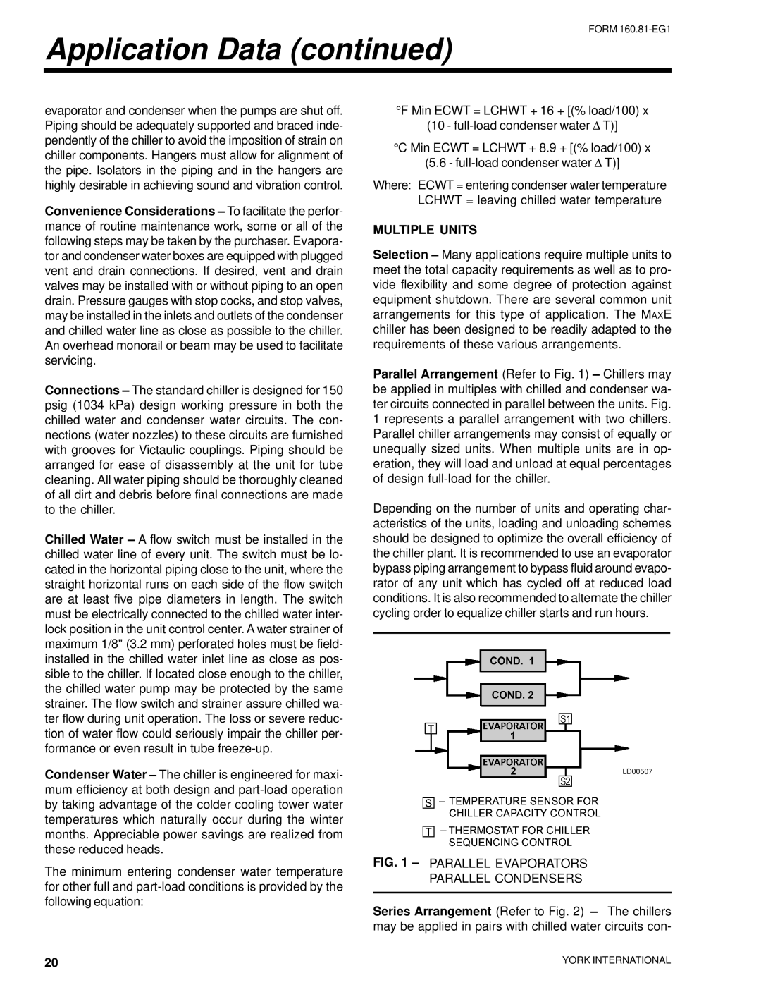
Parallel Arrangement (Refer to Fig. 1) – Chillers may be applied in multiples with chilled and condenser wa- ter circuits connected in parallel between the units. Fig. 1 represents a parallel arrangement with two chillers. Parallel chiller arrangements may consist of equally or unequally sized units. When multiple units are in op- eration, they will load and unload at equal percentages of design
Depending on the number of units and operating char- acteristics of the units, loading and unloading schemes should be designed to optimize the overall efficiency of the chiller plant. It is recommended to use an evaporator bypass piping arrangement to bypass fluid around evapo- rator of any unit which has cycled off at reduced load conditions. It is also recommended to alternate the chiller cycling order to equalize chiller starts and run hours.
LD00507
FIG. 1 – PARALLEL EVAPORATORS
PARALLEL CONDENSERS
Series Arrangement (Refer to Fig. 2) – The chillers may be applied in pairs with chilled water circuits con-
20 | YORK INTERNATIONAL |
|