FORM
Dimensions (Ft.-In.) – Nozzle Arrangements
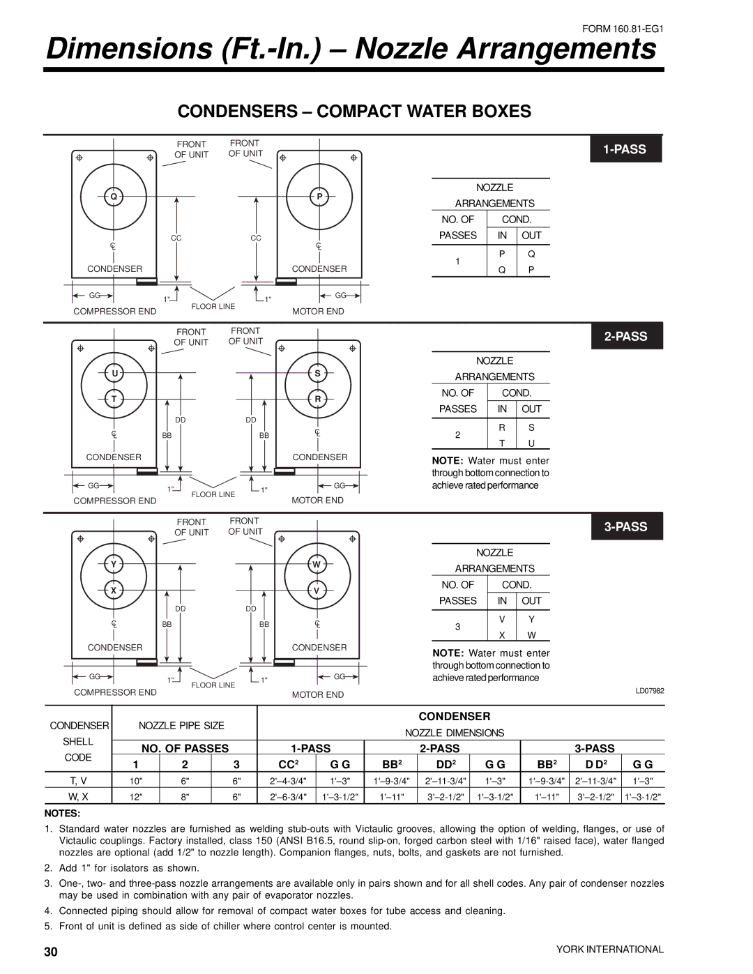
CONDENSERS – COMPACT WATER BOXES
FRONT | FRONT |
OF UNIT | OF UNIT |
1-PASS
NOZZLE
Q |
|
|
| P | ARRANGEMENTS | ||
|
|
|
|
| |||
|
|
|
|
| NO. OF | COND. | |
| CC | CC |
|
| PASSES | IN | OUT |
|
|
|
|
| 1 | P | Q |
CONDENSER |
|
|
| CONDENSER | Q | P | |
|
|
|
| ||||
GG | 1" |
| 1" | GG |
|
|
|
| FLOOR LINE |
|
|
|
| ||
COMPRESSOR END |
|
| MOTOR END |
|
|
| |
|
|
|
|
|
| ||
| FRONT | FRONT |
| |
| OF UNIT | OF UNIT |
| |
U |
|
|
| S |
T |
|
|
| R |
| DD |
| DD |
|
| BB |
| BB |
|
CONDENSER |
|
|
| CONDENSER |
GG | 1" |
| 1" | GG |
|
|
| ||
COMPRESSOR END | FLOOR LINE |
| MOTOR END | |
|
|
| ||
2-PASS
NOZZLE
ARRANGEMENTS
NO. OF | COND. | ||
PASSES | IN | OUT | |
2 | R | S | |
T | U | ||
| |||
NOTE: Water must enter through bottom connection to achieve rated performance
FRONT | FRONT |
| |||
OF UNIT | OF UNIT | ||||
| |||||
|
|
|
|
| |
NOZZLE
Y |
|
| W |
X |
|
| V |
| DD | DD |
|
| BB | BB |
|
CONDENSER |
|
| CONDENSER |
GG | 1" | 1" | GG |
|
| ||
COMPRESSOR END |
| FLOOR LINE |
|
|
| MOTOR END |
ARRANGEMENTS
NO. OF | COND. | ||
PASSES | IN | OUT | |
3 | V | Y | |
X | W | ||
| |||
NOTE: Water must enter through bottom connection to achieve rated performance
LD07982
CONDENSER | NOZZLE PIPE SIZE |
|
|
|
| CONDENSER |
|
|
| |||
|
|
| NOZZLE DIMENSIONS |
|
|
| ||||||
SHELL |
|
|
|
|
|
|
|
|
| |||
NO. OF PASSES |
|
|
|
|
| |||||||
CODE |
|
|
|
|
| |||||||
1 | 2 |
| 3 | CC2 | G G | BB2 | DD2 | G G | BB2 | D D2 | G G | |
|
| |||||||||||
T, V | 10" | 6" |
| 6" |
|
| ||||||
W, X | 12" | 8" |
| 6" |
| |||||||
NOTES:
1.Standard water nozzles are furnished as welding
2.Add 1" for isolators as shown.
3.
4.Connected piping should allow for removal of compact water boxes for tube access and cleaning.
5.Front of unit is defined as side of chiller where control center is mounted.
30 | YORK INTERNATIONAL |
|