Installation Drawings
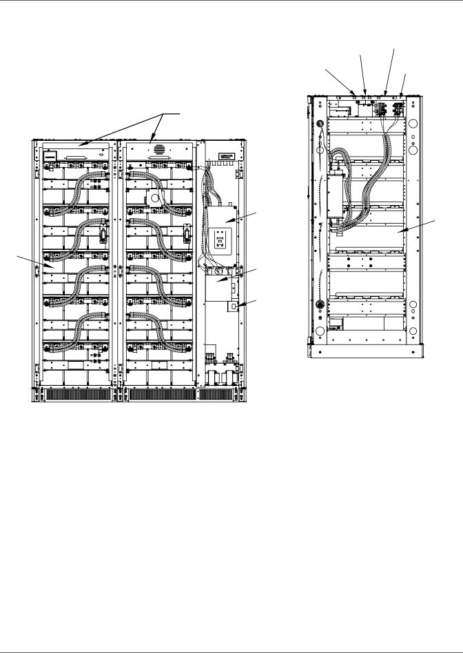
Figure 12 Front Terminal Battery Cabinet main components, layout
|
| High Voltage | Positive | ||
|
| Battery Bus | |||
|
| Control Cable |
|
| |
|
| Trough |
| Negative | |
Low Voltage |
| Battery Bus | |||
Control Cable |
| ||||
|
| ||||
Trough |
|
| |||
|
|
|
|
|
|
Location for Optional |
|
Alber Monitoring Equipment |
|
Front |
|
Battery | Battery |
Breaker | |
| Typ. |
Battery |
|
Typ. |
|
Battery |
|
Interface |
|
Board (BIB) |
|
Ground Bus |
|
| Right Side View |
| With Panels Removed |
Front View
Liebert® NX™ | 16 |