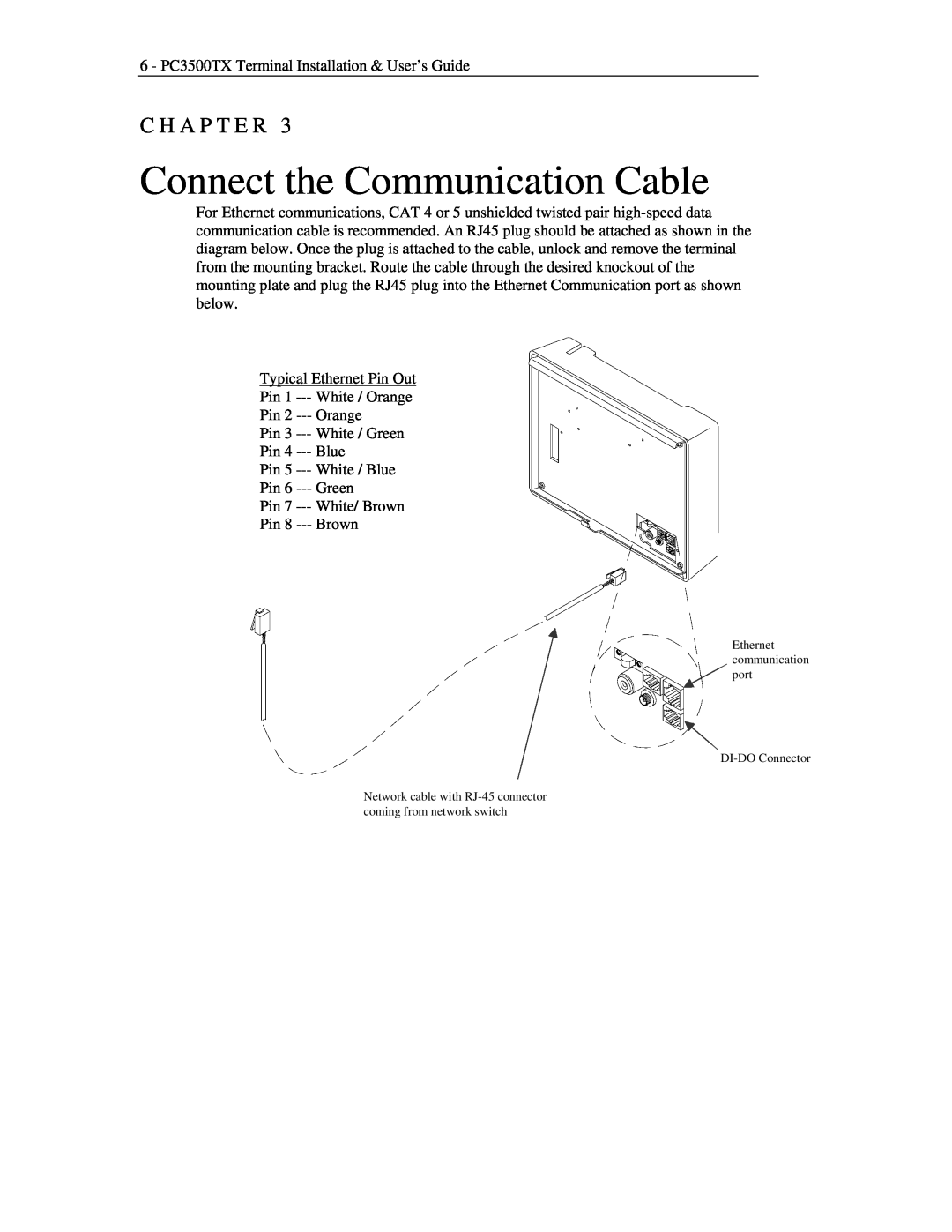
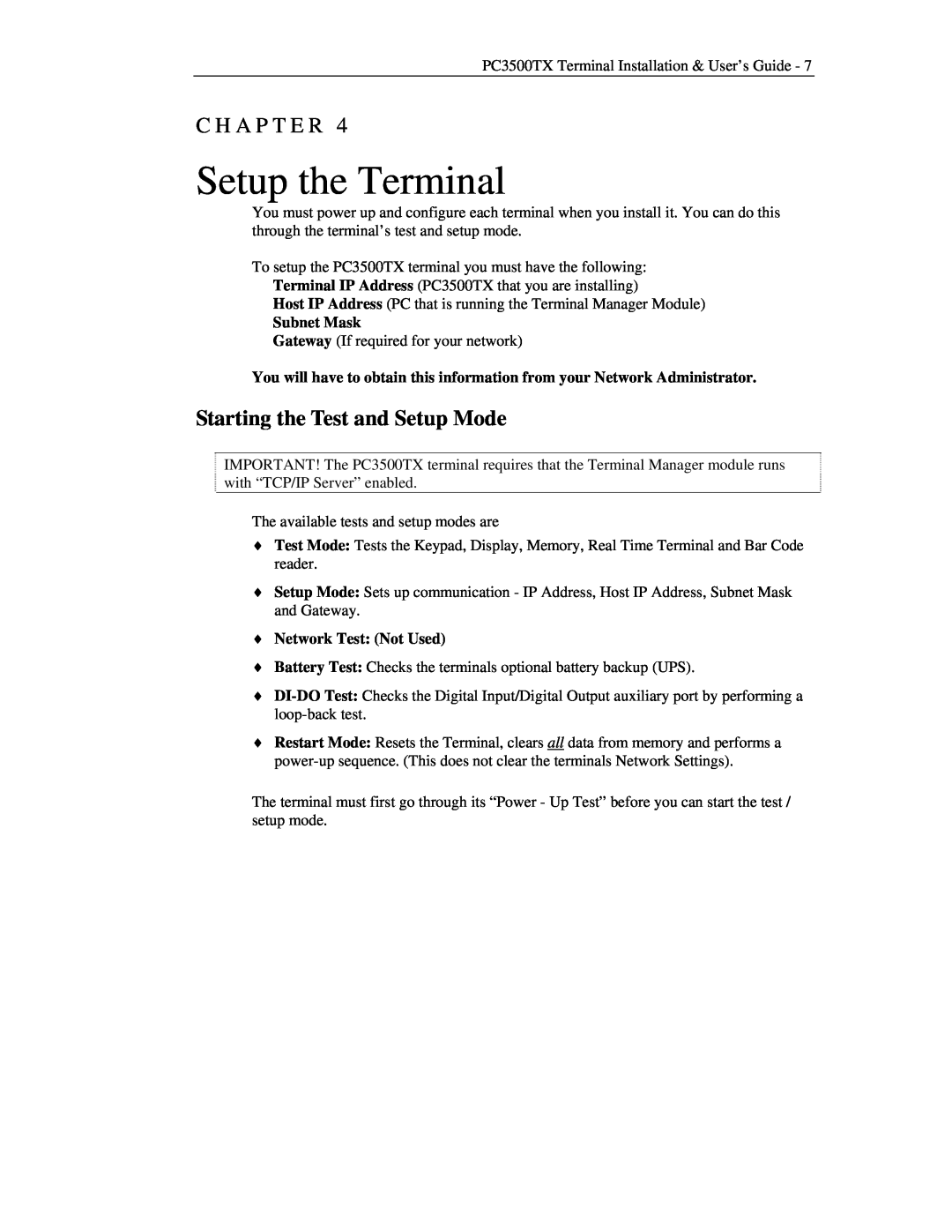
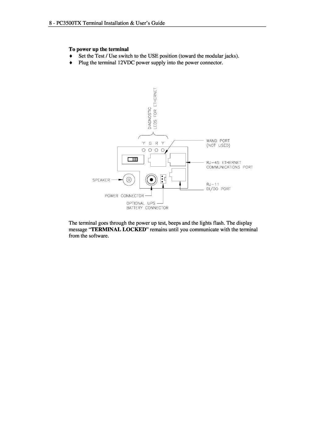
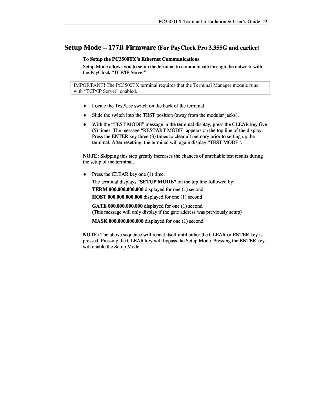
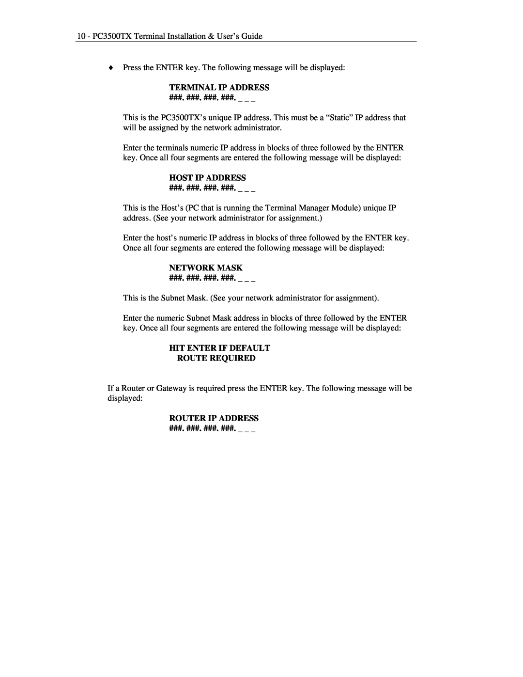
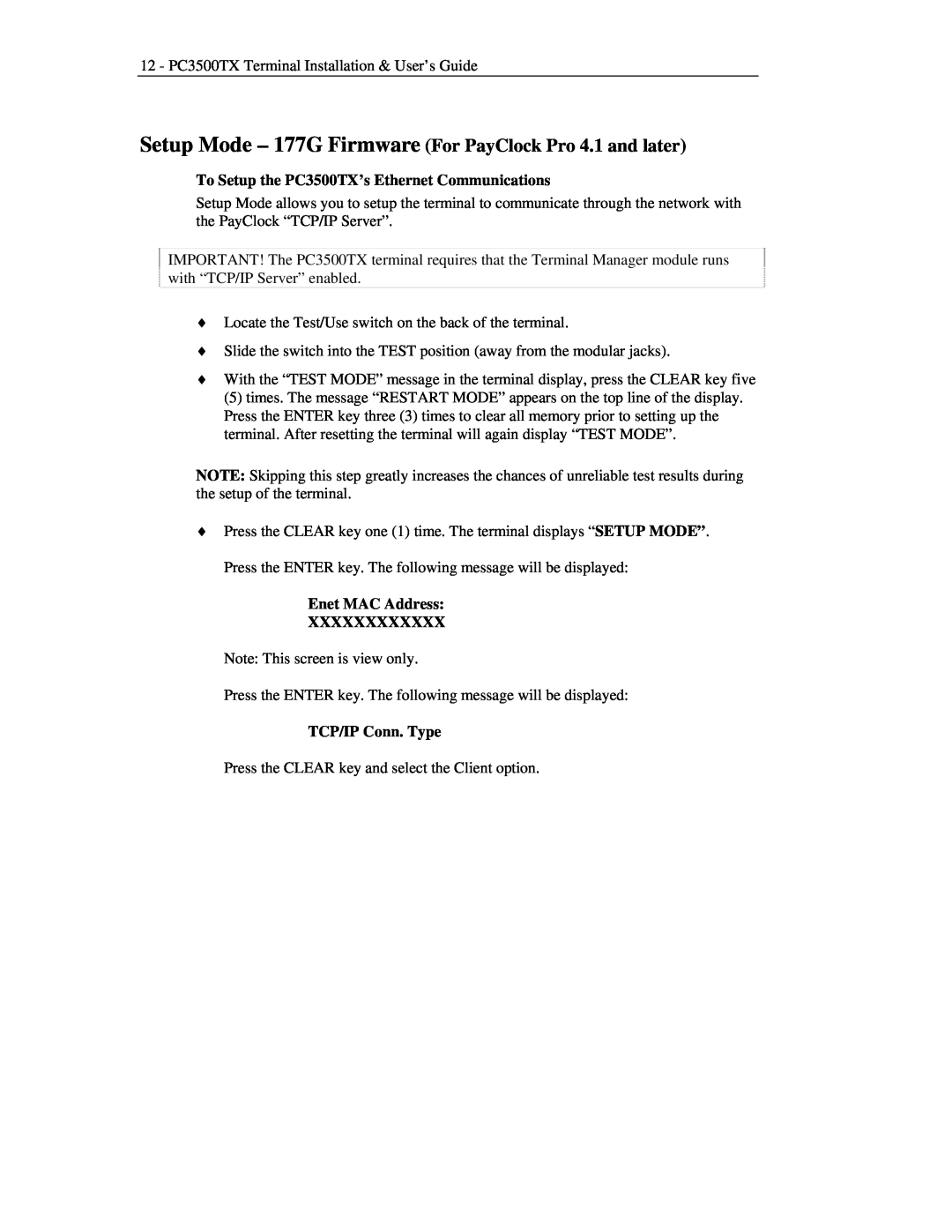
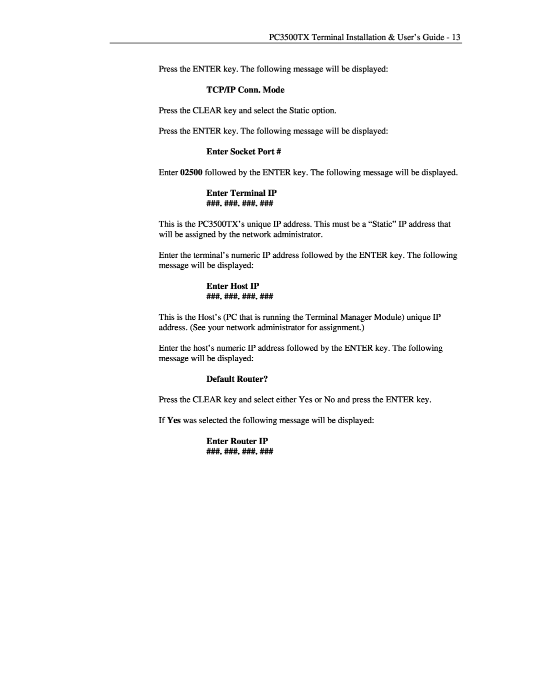
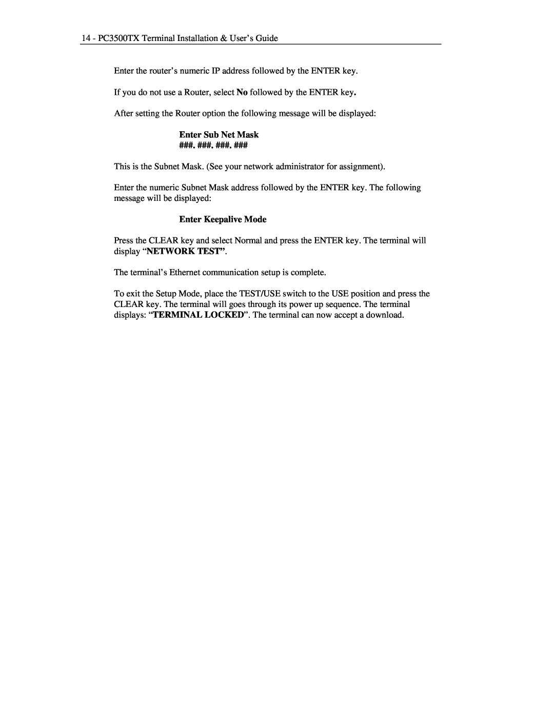
Lathem PC3500TX manual Optional Signal Device, General Specifications, A P P E N D I X B

Page 26
A P P E N D I X B

22 - PC3500TX Terminal Installation & User’s Guide

A P P E N D I X B

Optional Signal Device

With a bell relay, you can program when bells or other devices will ring using the Bell Wizard in your Terminal Manager software. Call Lathem to purchase a bell relay. You should have a qualified/certified electrician connect your signaling devices to ensure proper connections and prevent damage to your equipment. Note: The PC3500TX relay is only a switching device and does not supply power to the ringer.

To connect your signaling device(s)

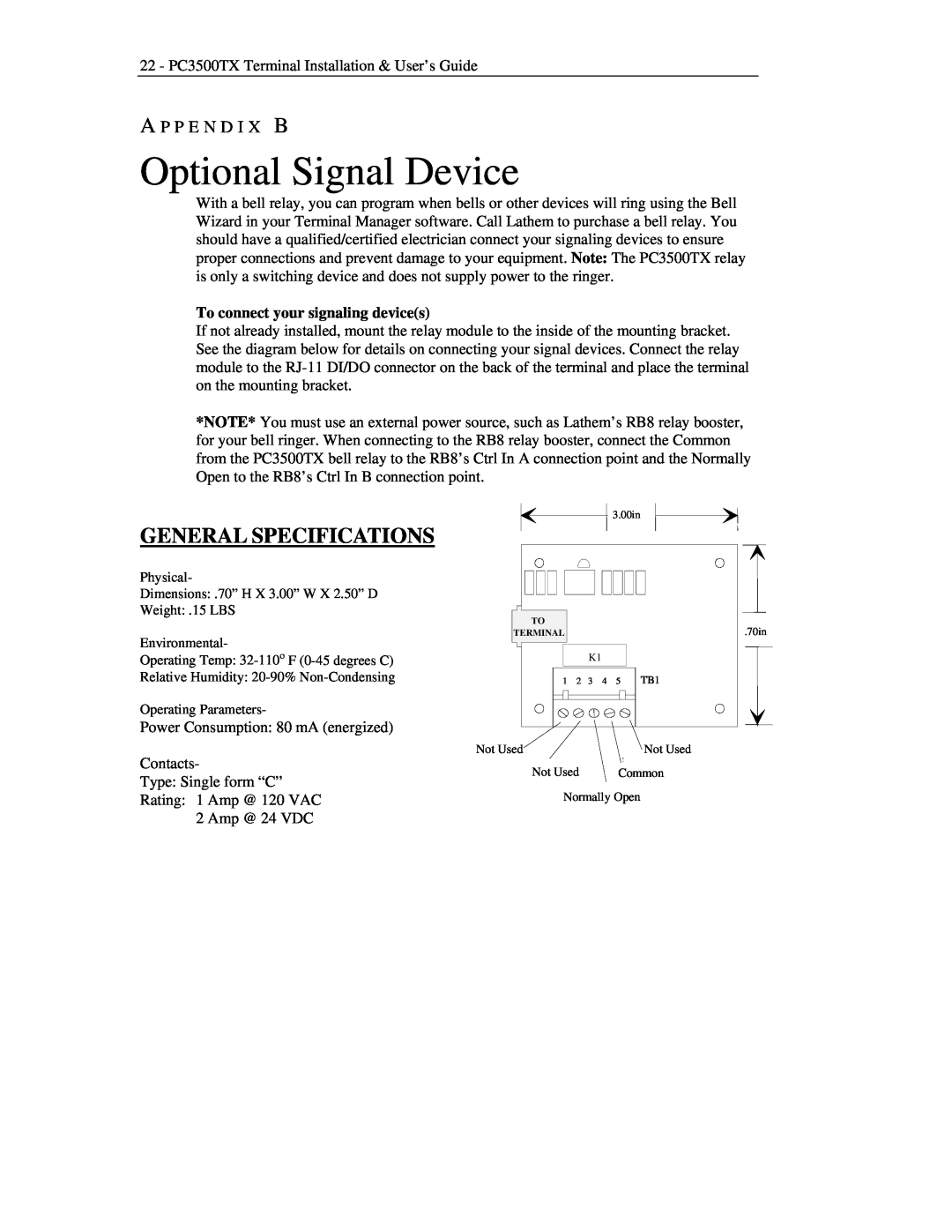
If not already installed, mount the relay module to the inside of the mounting bracket. See the diagram below for details on connecting your signal devices. Connect the relay module to the RJ-11 DI/DO connector on the back of the terminal and place the terminal on the mounting bracket.

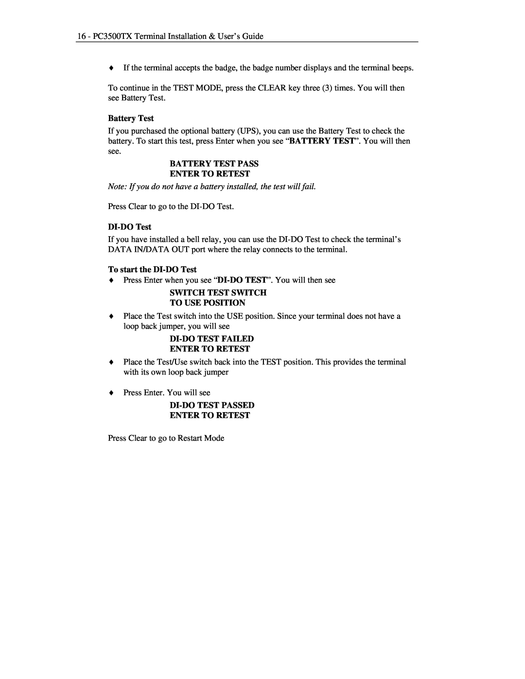
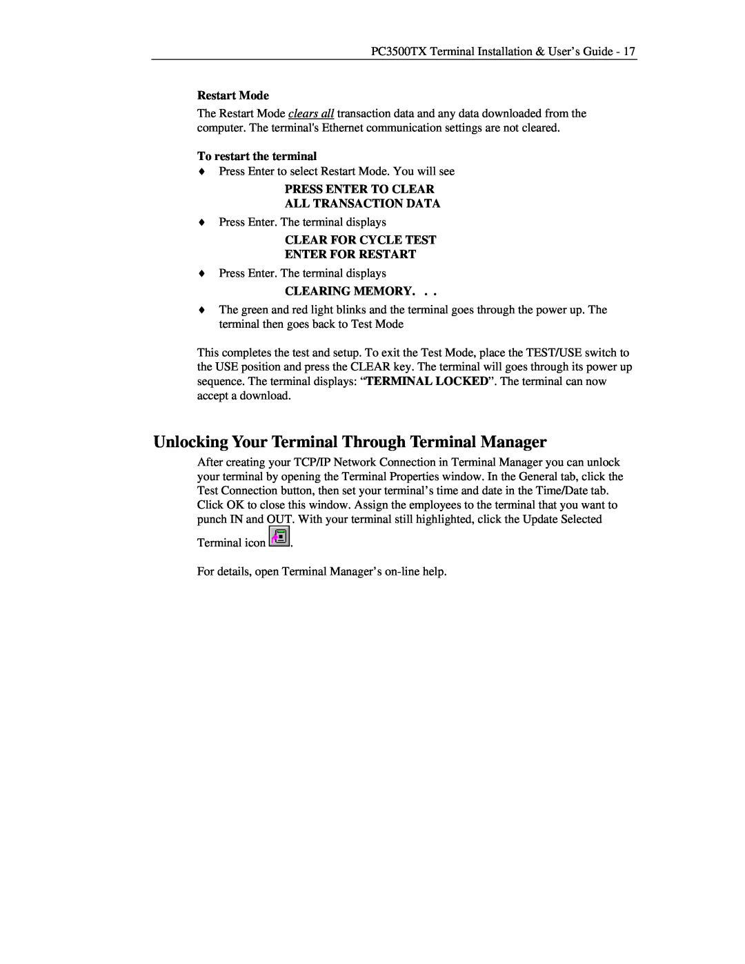
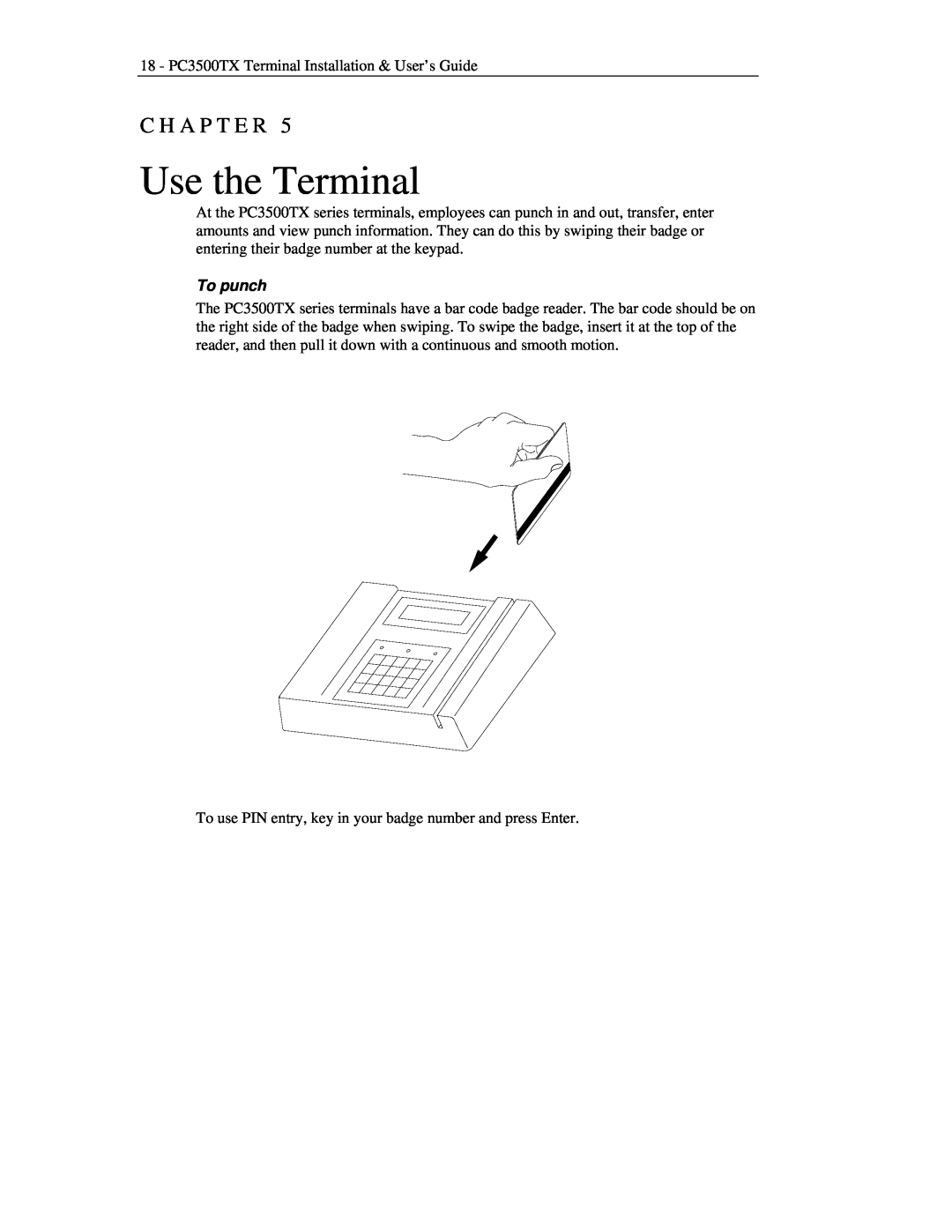
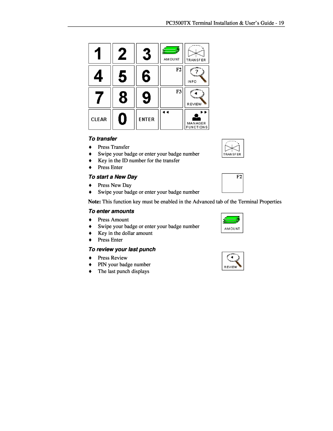
*NOTE* You must use an external power source, such as Lathem’s RB8 relay booster, for your bell ringer. When connecting to the RB8 relay booster, connect the Common from the PC3500TX bell relay to the RB8’s Ctrl In A connection point and the Normally Open to the RB8’s Ctrl In B connection point.

GENERAL SPECIFICATIONS

Physical-

Dimensions: .70” H X 3.00” W X 2.50” D

Weight: .15 LBS

Environmental-

Operating Temp: 32-110οF (0-45 degrees C)

Relative Humidity: 20-90% Non-Condensing

Operating Parameters-

Power Consumption: 80 mA (energized)

Contacts-

Type: Single form “C”

Rating: 1 Amp @ 120 VAC 2 Amp @ 24 VDC


3.00in


TO


TERMINAL


K1


1

2

3

4

5

TB1

Not Used


Not Used

Not Used


Common

Normally Open

.70in
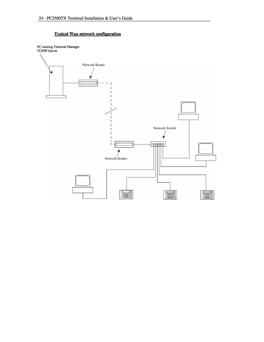
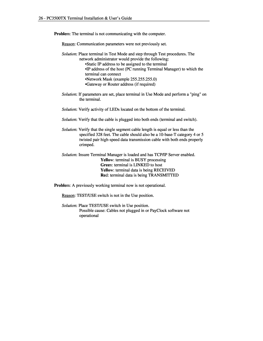
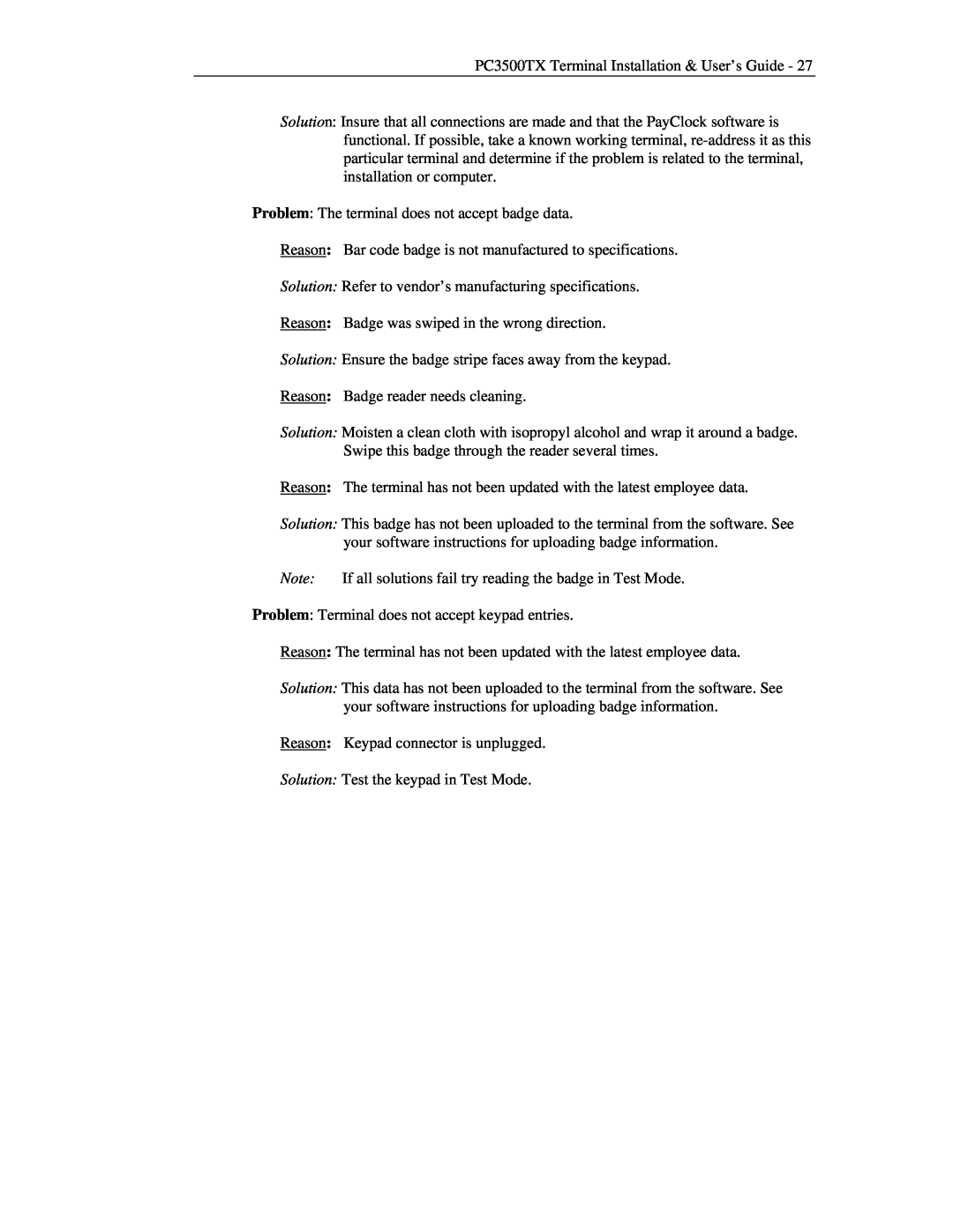
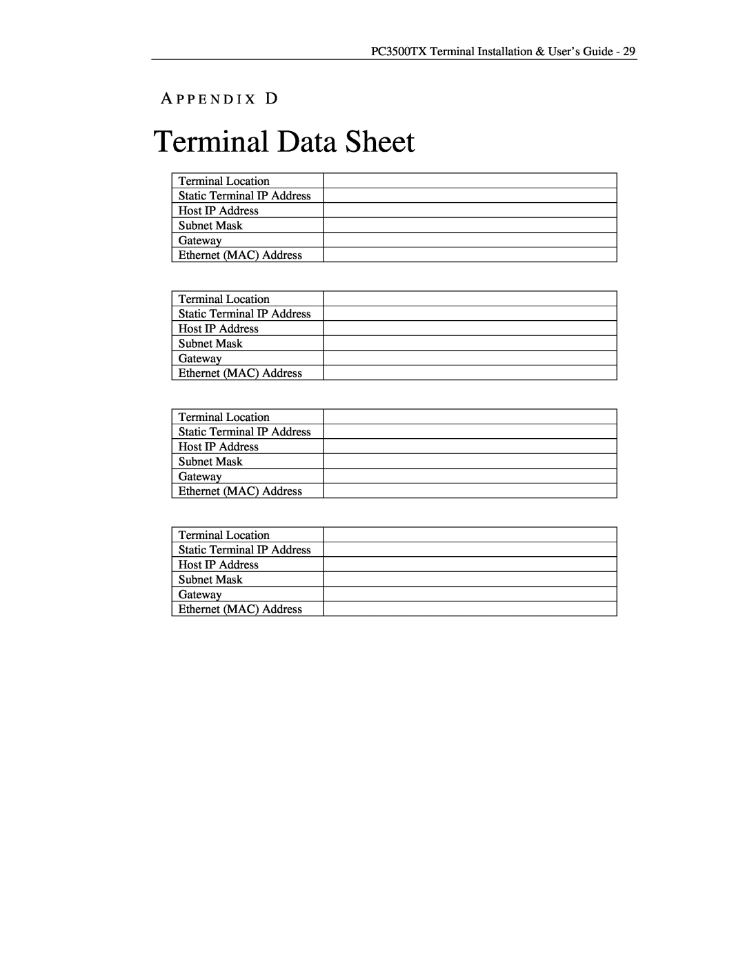
Image 26
Contents PC3500TX Terminal Installation & User’s GuideLimited One-Year Limited Warranty PayClock, Lathem and the Lathem logo are registered trademarks of Lathem Time Corporation. Other product names OPTIONAL SIGNAL DEVICE SETUP THE TERMINALINSTALL/REPLACE THE OPTIONAL BACKUP BATTERY NETWORK WIRING TOPOLOGIESC H A P T E R Features and SpecificationsWelcome PC3500TX NOTICE - For Firmware 177B and EarlierPower Surges and Spikes Note about Lithium BatteryMount the Terminal Pre-Terminal InstallationMounting the Terminal To install the mounting bracket Turn the key clockwise to lock the terminal in place Connect the Communication Cable Subnet Mask Setup the TerminalStarting the Test and Setup Mode Network Test Not UsedPlug the terminal 12VDC power supply into the power connector To power up the terminal8 - PC3500TX Terminal Installation & User’s Guide Setup Mode - 177B Firmware For PayClock Pro 3.355G and earlier To Setup the PC3500TX’s Ethernet CommunicationsHOST IP ADDRESS ###. ###. ###. ### HIT ENTER IF DEFAULT ROUTE REQUIREDTERMINAL IP ADDRESS ###. ###. ###. ### NETWORK MASK ###. ###. ###. ###ENETADD=XXXXXXXXXXXX SETUP COMPLETE TCP/IP Conn. Type Setup Mode - 177G Firmware For PayClock Pro 4.1 and laterEnet MAC Address XXXXXXXXXXXX Enter Socket Port # Default Router?TCP/IP Conn. Mode Enter Terminal IP ###. ###. ###. ###Enter Sub Net Mask ###. ###. ###. ### Enter Keepalive Mode“TEST MODE” PROG# Test ModeTo start the Test Mode TEST MODE 128 YYNote If you do not have a battery installed, the test will fail Battery TestBATTERY TEST PASS ENTER TO RETEST SWITCH TEST SWITCH TO USE POSITIONTo restart the terminal Unlocking Your Terminal Through Terminal ManagerRestart Mode PRESS ENTER TO CLEAR ALL TRANSACTION DATAUse the Terminal To punchTo enter amounts To transferTo start a New Day To review your last punchSupervisor Functions When you see BADGE FOR SUPERVISOR OVERIDE, swipe your badgeWhen you see ENTER ASSOCIATES BADGE, swipe the employee’s badge To see employee InfoInstall/Replace the Optional Backup Battery A P P E N D I X ATo connect your signaling devices Optional Signal DeviceGENERAL SPECIFICATIONS A P P E N D I X BA P P E N D I X C Network Wiring TopologiesTypical Lan network configuration Typical Wan network configuration 24 - PC3500TX Terminal Installation & User’s GuideTroubleshooting the Terminal Problem A previously working terminal now is not operational 26 - PC3500TX Terminal Installation & User’s GuideProblem The terminal is not communicating with the computer Reason TEST/USE switch is not in the Use positionSolution Refer to vendor’s manufacturing specifications Problem The terminal does not accept badge dataReason Bar code badge is not manufactured to specifications Solution Ensure the badge stripe faces away from the keypadClick OK to save the changes Update the terminal with the changes 28 - PC3500TX Terminal Installation & User’s GuideSolution Open the PC3500TX’s Terminal Properties in Terminal Manager Select the Advanced tabTerminal Data Sheet A P P E N D I X D