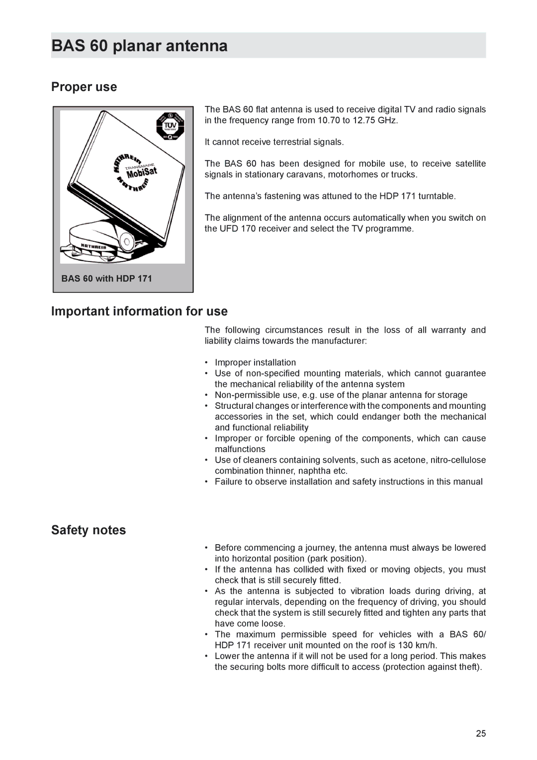
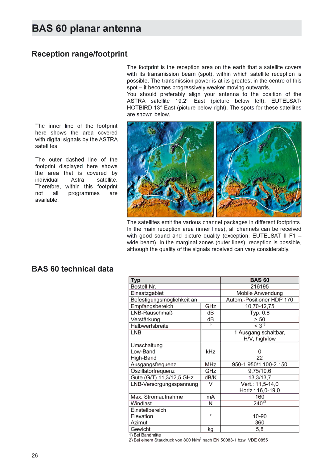
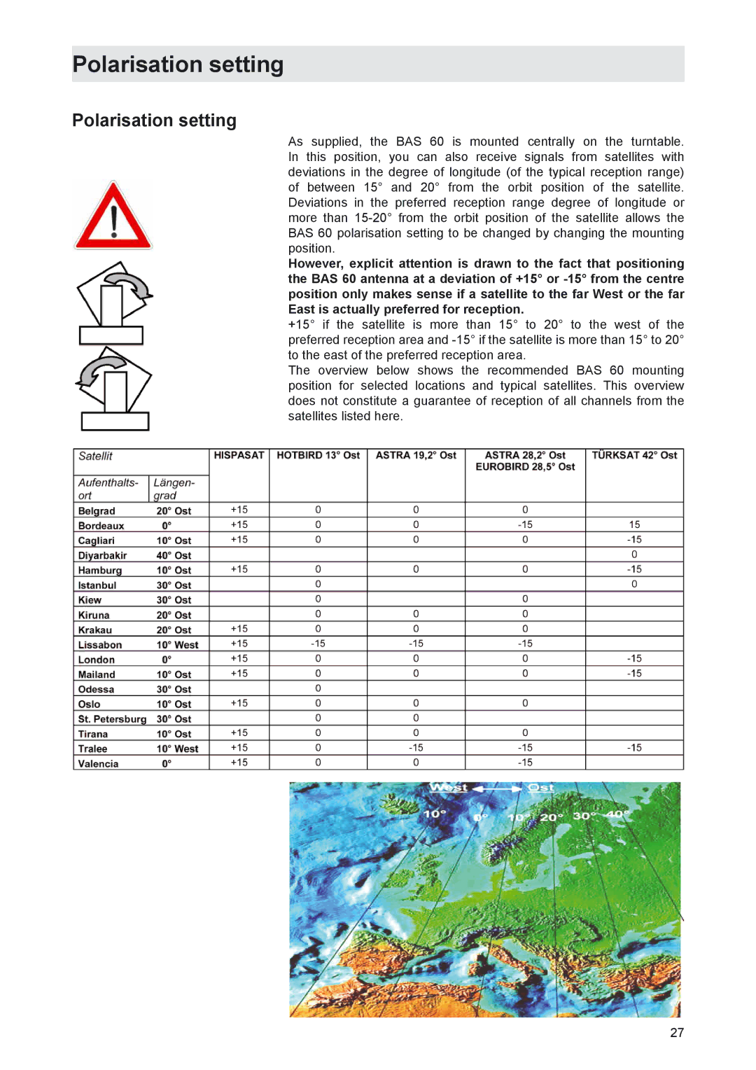
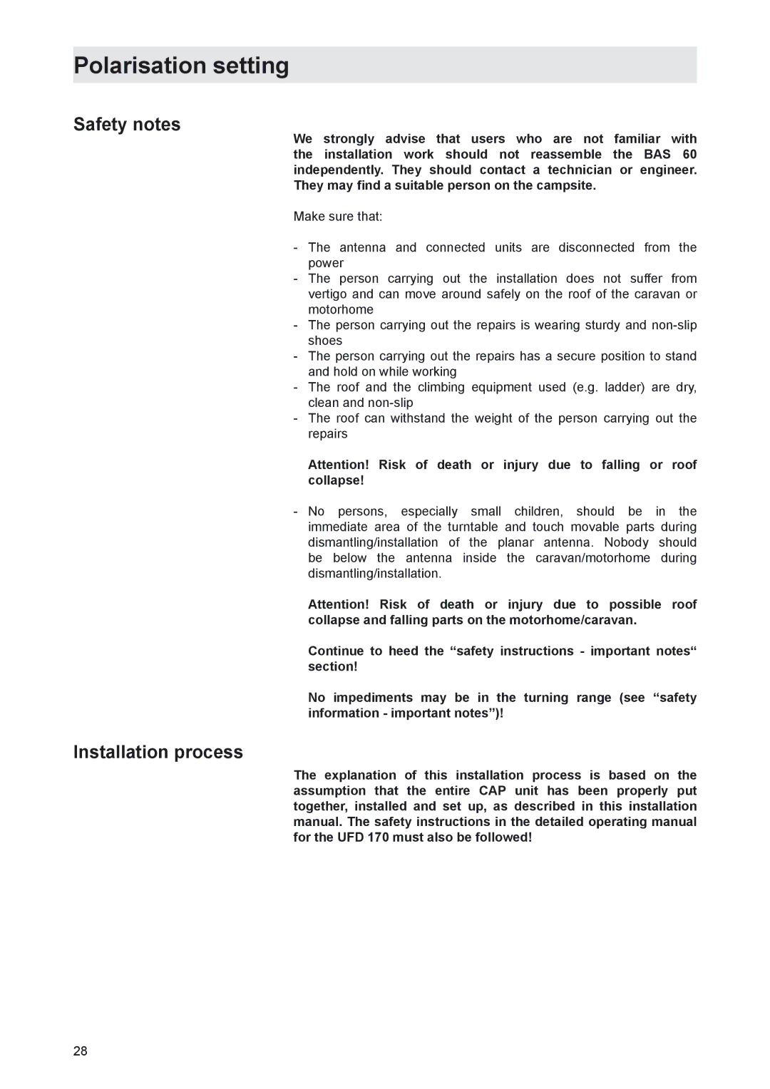
Kathrein MobiSet 3 CAP 310, CAP 210 Installation and connection, Required tools and equipment

Page 12

Installation and connection

Required tools and equipment

Circular cutter, Ø 38 mm

Flat-bladed screwdriver for M5 screws

Drilling machine

Galvanised tallow drop screws, depending on roof structure (Ø: 5 mm, sheet metal screws D 7981, depending on roof panel structure) or tallow drop screws D 7985 with shims and nuts

Twist drill, Ø 2.5 or 5.5 mm

Round file and/or emery paper

Cleaning agent

Fork or ring bolt with width of 10 and 11 mm

Knife

Cross recess screwdriver for M3 and M5 screws

Torque wrench between 6 and 11 Nm

Hexagon socket screw key (5 mm)

Two wooden beams for supporting turntable

Unpacking and preparation

Remove the turntable from the packaging. Retain the original packaging, as if it is necessary to send the unit for repair transport damage cannot be ruled out and the manufacturer accepts no liability for possible damage.

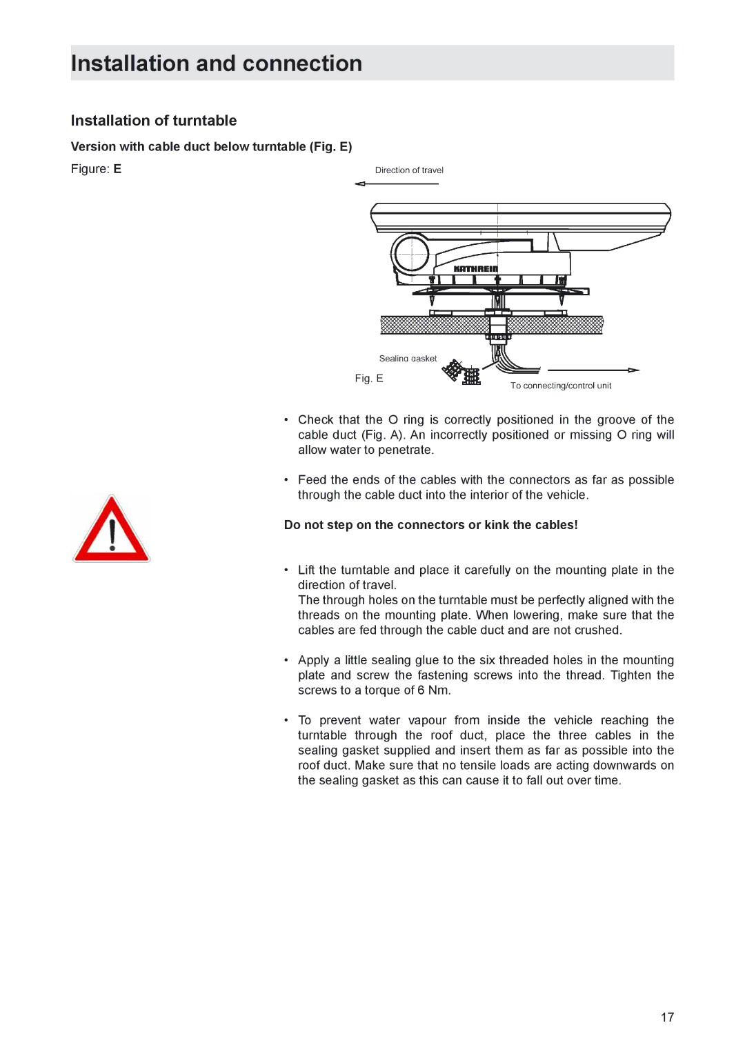
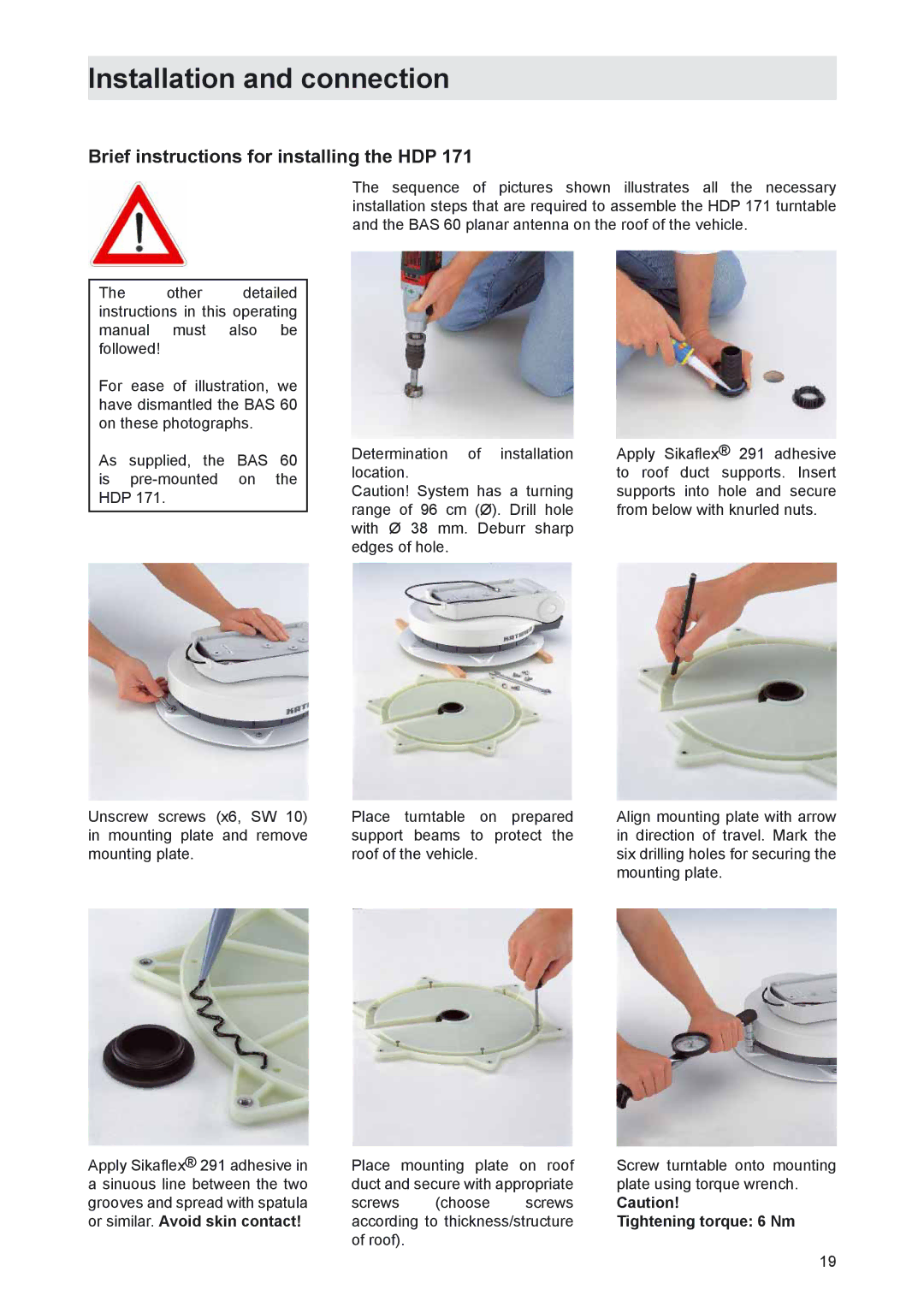
Loosen the six fastening screws (width: 10 mm). Carefully lift the turntable off the mounting plate and place it on the prepared support beams. It must be ensured that the cable running out of the underside of the turntable is not crushed.

Selecting the installation location

Essentially, the cable lengths of the MobiSet 3 digital CAP 310 components allow you a free choice of installation location on your caravan or motorhome.

However, you should take note of the following points:

Before installation, you should find out whether the operating manual for your vehicle permits the fitting of non-vehicle specific parts or what requirements need to be met in order to do so.

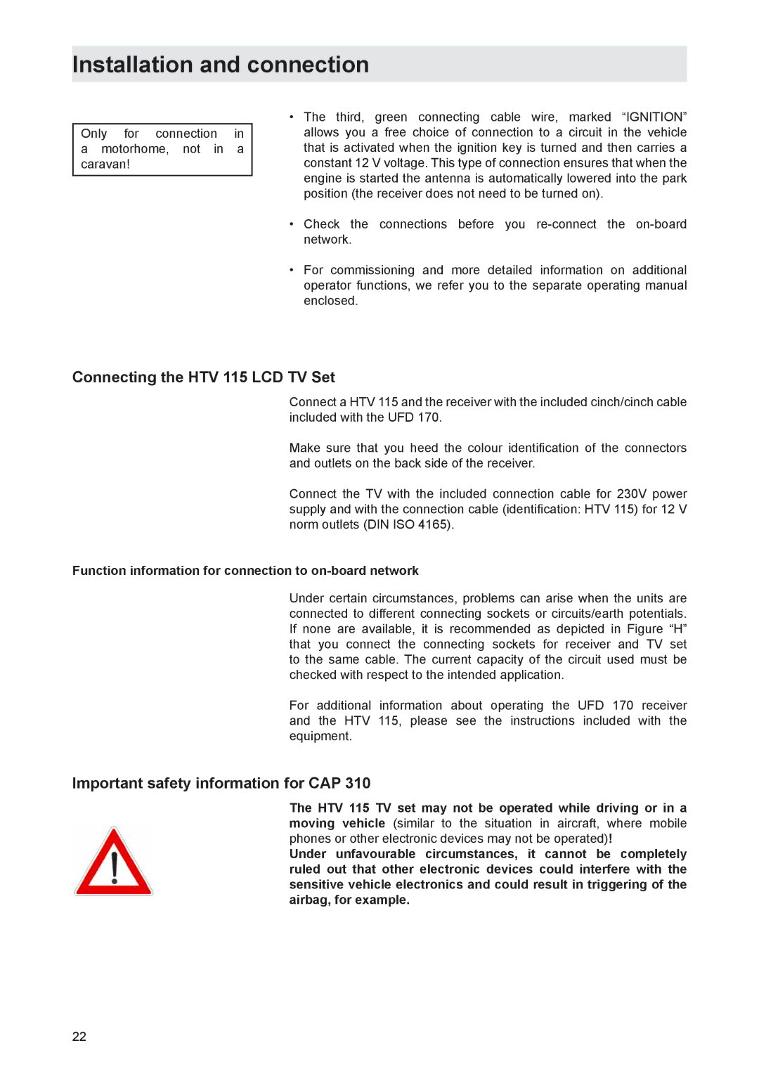
For direct satellite reception, there should not be any obstructions between the antenna and the satellite. Therefore, make sure that the antenna is not shadowed by roof extensions such as baggage carriers, air conditioning units, solar panels, etc. The problem of shadowing applies also for the selection of the parking place for your vehicle. For interference-free satellite reception, the antenna needs an imaginary free view to the South at an angle of between 15° and 55° (depending on location) to the horizontal.

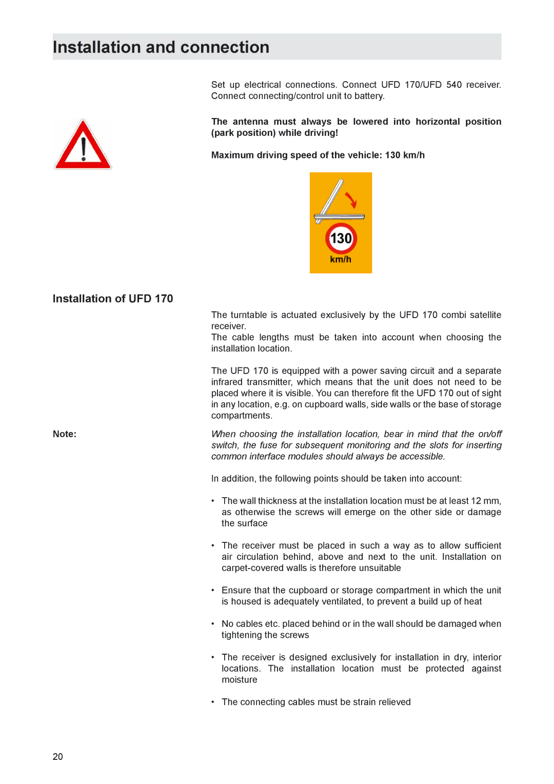
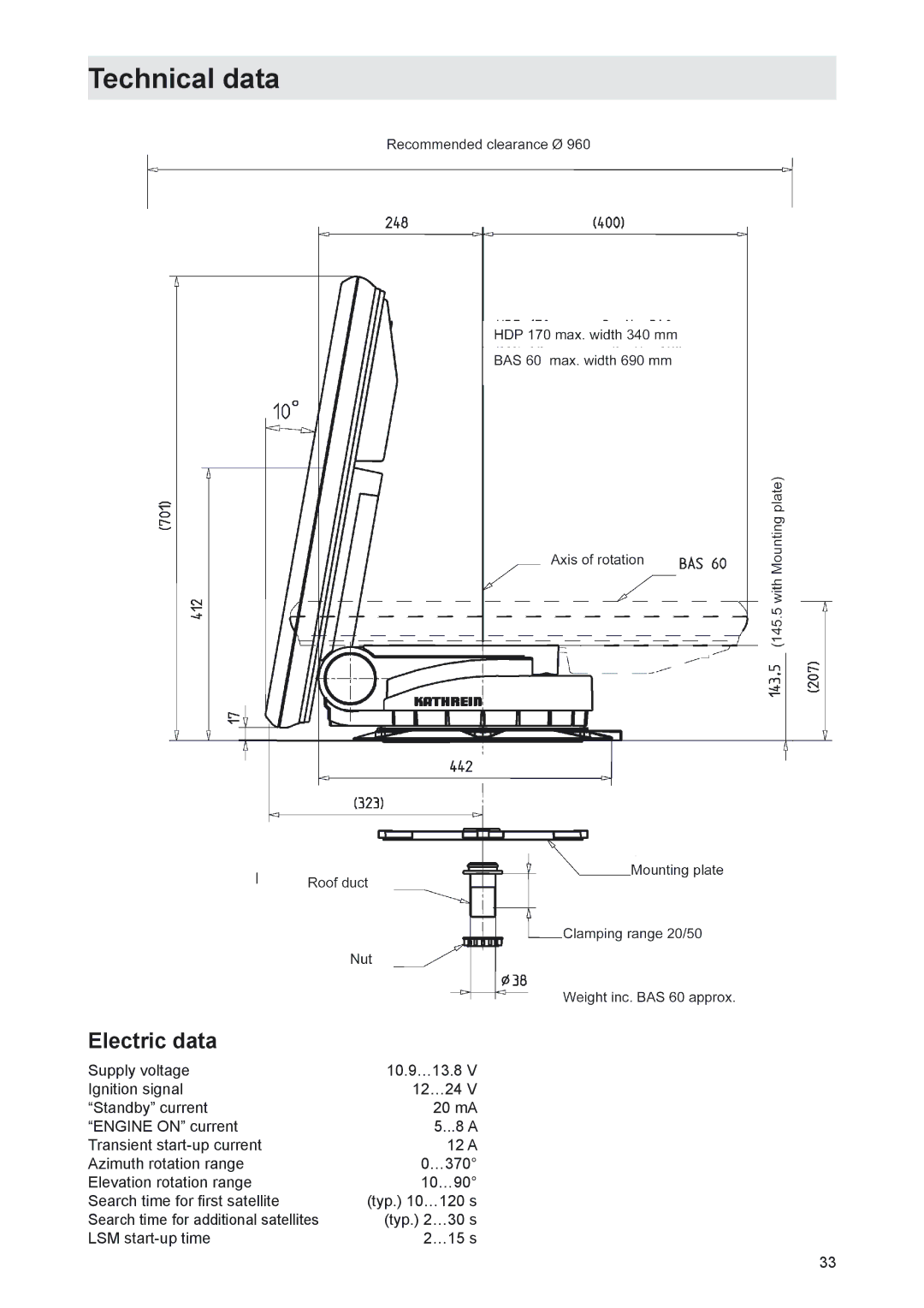
The turntable has, together with the BAS 60 planar antenna, a circular action area with a diameter of approx. 96 cm. Make sure that there are no roof extensions within this range (collision danger).

Choose a mounting position on the roof that is as flat as possible as, depending on the location of the vehicle, roof inclines greater than 10° may lead to problems searching for the satellite.

12
Image 12
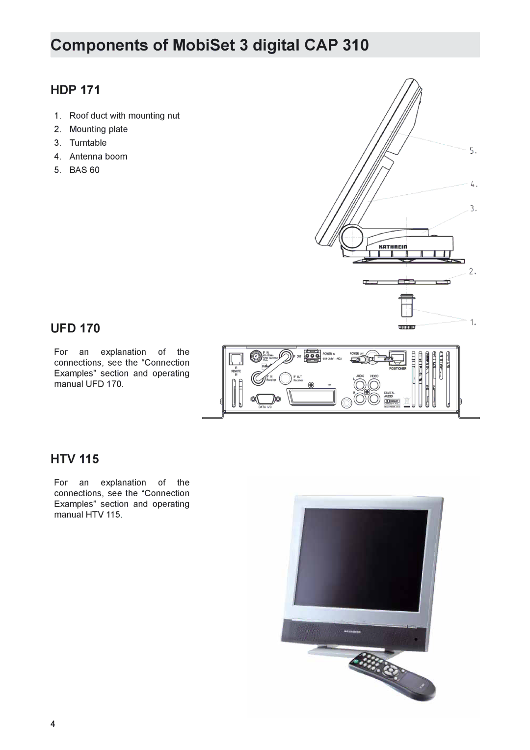
Contents MobiSet 2 digital CAP Mobi Set 3 digital CAP Important information about MobiSet 2 digital CAP HTV 115 LCD/TFT television set is only included with the CAPForeign language installation instructions Components of MobiSet 3 digital CAP HDPUFD HTVProduct package Product packageInstallation instructions Proper useProper use Intended purposeSafety instructions important notes Safety during installation workProper installation and safety Fundamental informationSealing glue Road Traffic Licensing Regulations StVZO Power supply, fusing Checks before commencing a journeyCleaning the antenna Safety precautions during installationLowering the antenna while driving Safety instructions important notes Installation and connection Selecting the installation locationRequired tools and equipment Unpacking and preparationCables may not be cut, as otherwise the proper functioning Installation steps Installation of cable duct and mounting plateInstallation and connection Installation and connection Installation of turntable Do not step on the connectors or kink the cablesVersion with cable duct below turntable Fig. E Version with external cable duct Fig. F Brief instructions for installing the HDP Tightening torque 6 NmInstallation of UFD Common interface modules should always be accessibleLaying cables and connecting the turntable HDP Connecting the UFD 170 to the on-board power networkConnecting the HTV 115 LCD TV Set Important safety information for CAPFunction information for connection to on-board network Connection example motorhome 12 V battery connection UFD Connection example caravan 230 V battery connection UFD Safety notes BAS 60 planar antennaImportant information for use BAS 60 with HDPBAS 60 technical data Reception range/footprintPolarisation setting Polarisation settingInstallation process Motorhome/caravan On the turntableView after installation +15 Middle standardAddress of the service centre Electronic Service Chiemgau GmbH BahnhofstrasseDismantling for servicing DismantlingTechnical data Dimensions mmElectric data Sikaflex 291 data sheet Sikaflex 291 technical data sheet Declaration of conformity