Kathrein MobiSet 3 CAP 310, CAP 210 Cables may not be cut, as otherwise the proper functioning

Page 13

Installation and connection


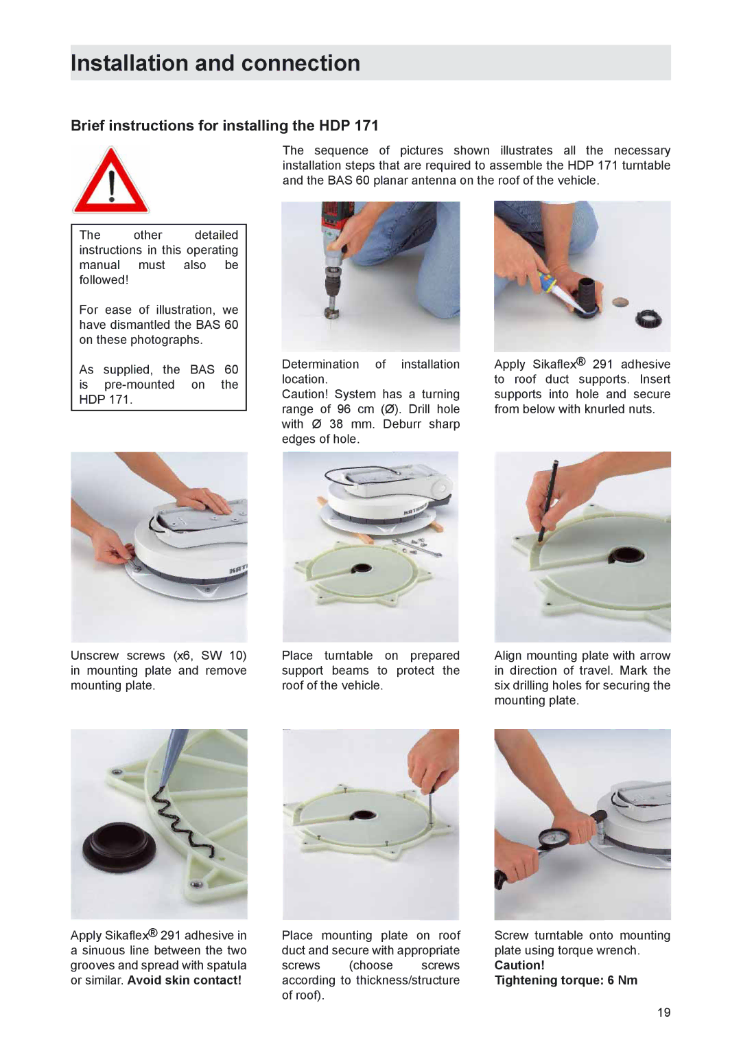
To ensure secure adhesion, the height difference of the roof curve


may not be more than 1 cm over a length of 2 m, as otherwise the


gap between the roof and the mounting plate would be too big to be


filled by the sealing glue.


As the vehicle is constantly subjected to vibration loads during


travel, the roof below the antenna unit is also subject to significant


loads. Please note given the nature and capacity of your vehicle roof


(see also operating manual for the vehicle) that the weight of the


antenna unit is approx. 14.5 kg. In case of doubt, consult a qualified


dealer or your vehicle’s manufacturer.


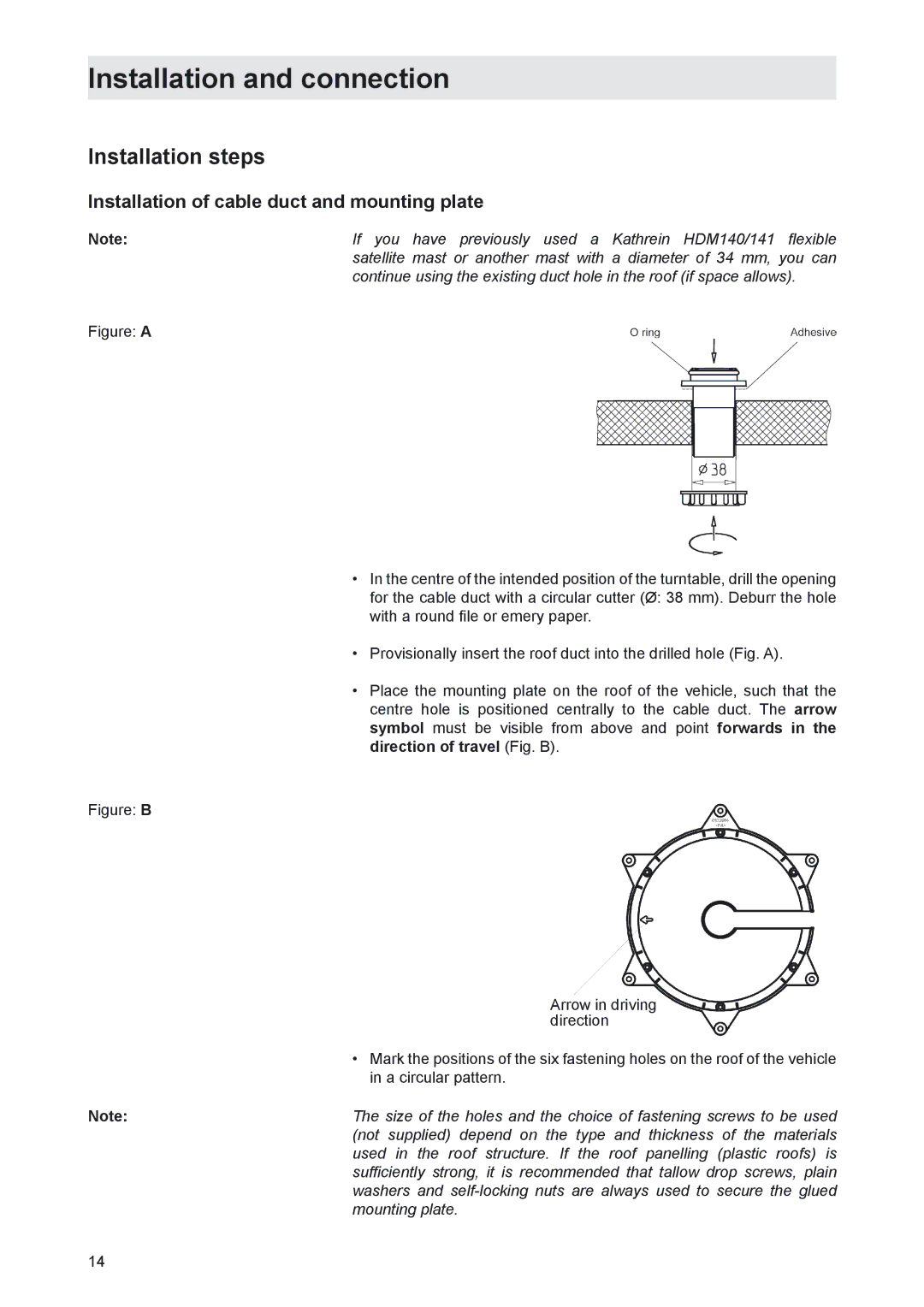
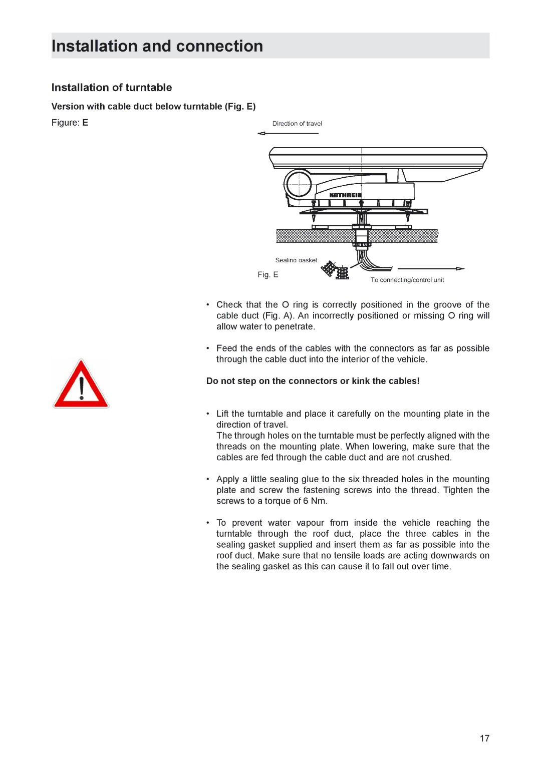
The roof duct provides a waterproof channel to feed the three


connecting cables (antenna, control unit and power supply cables)


into the interior of the vehicle directly underneath the turntable. If you


prefer a different method of laying the cables, they can be run out


of the rear of the turntable via the channel provided in the mounting


plate. The cables must then be run along the roof of the vehicle in a


protected cable duct (not supplied).

Note:

The cables may not be cut, as otherwise the proper functioning of


the unit can no longer be guaranteed.

13

Image 13
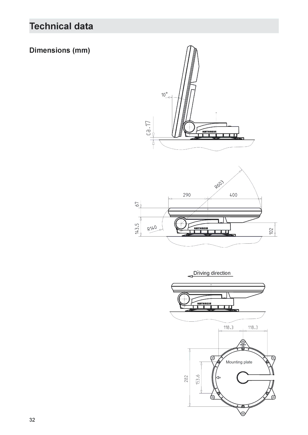
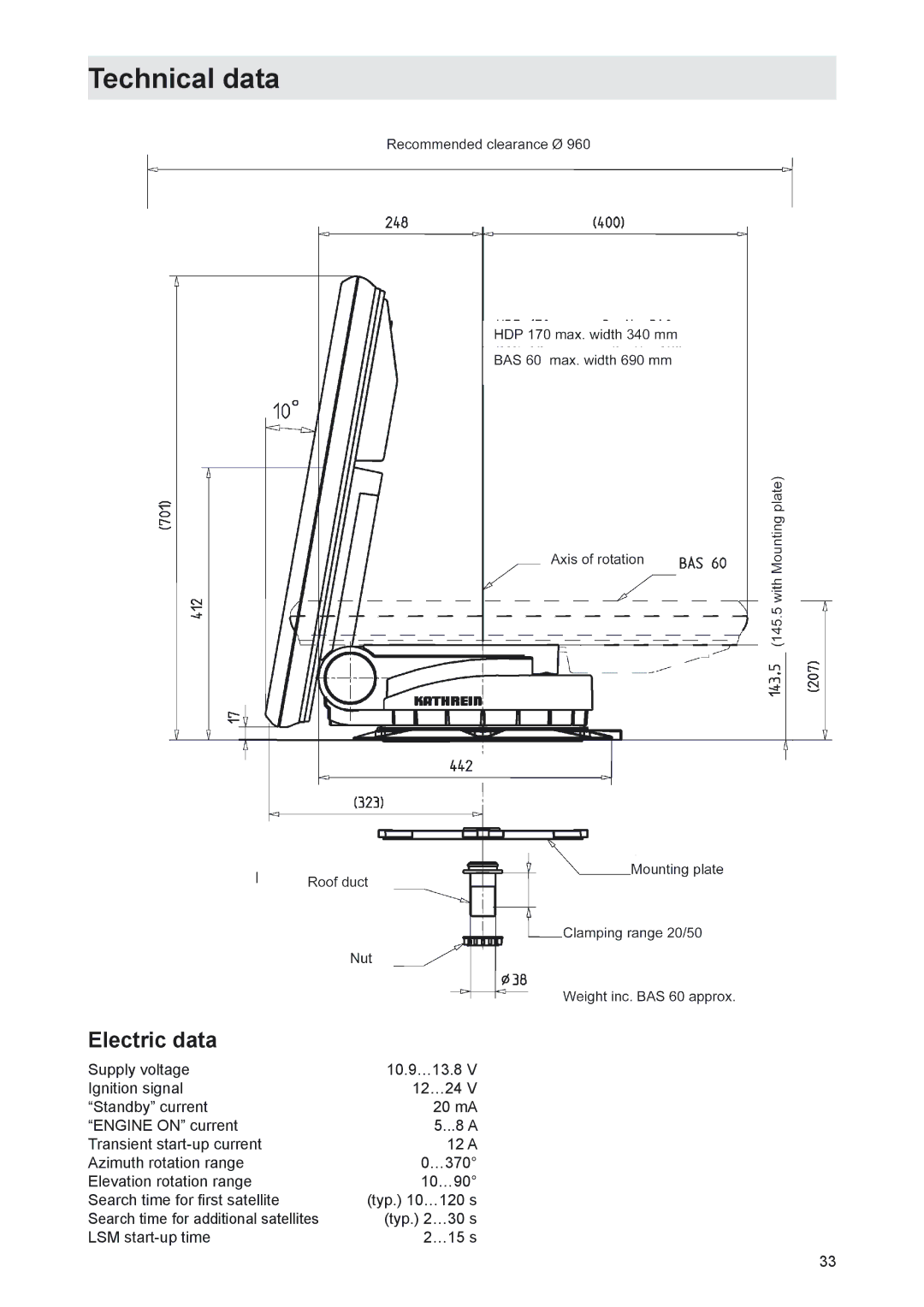
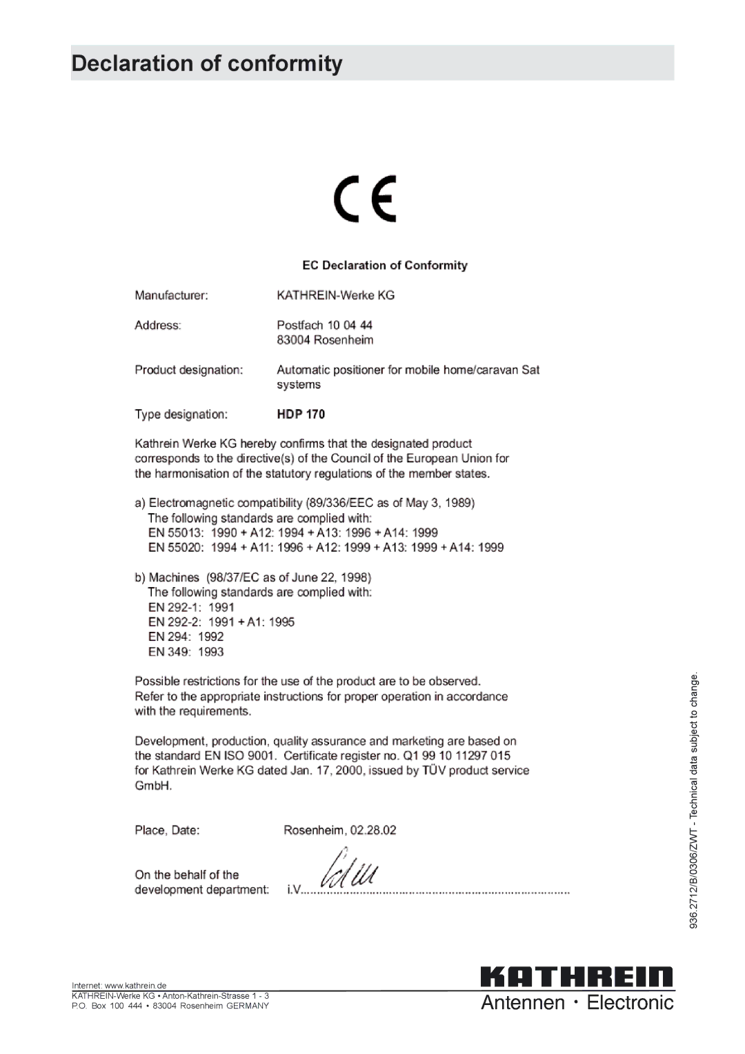
Contents MobiSet 2 digital CAP Mobi Set 3 digital CAP HTV 115 LCD/TFT television set is only included with the CAP Important information about MobiSet 2 digital CAPForeign language installation instructions HDP Components of MobiSet 3 digital CAPUFD HTVProduct package Product packageProper use Installation instructionsProper use Intended purposeSafety during installation work Safety instructions important notesFundamental information Proper installation and safetySealing glue Road Traffic Licensing Regulations StVZOChecks before commencing a journey Power supply, fusing Safety precautions during installation Cleaning the antenna Lowering the antenna while driving Safety instructions important notes Selecting the installation location Installation and connectionRequired tools and equipment Unpacking and preparationCables may not be cut, as otherwise the proper functioning Installation of cable duct and mounting plate Installation stepsInstallation and connection Installation and connection Do not step on the connectors or kink the cables Installation of turntableVersion with cable duct below turntable Fig. E Version with external cable duct Fig. F Tightening torque 6 Nm Brief instructions for installing the HDPCommon interface modules should always be accessible Installation of UFDConnecting the UFD 170 to the on-board power network Laying cables and connecting the turntable HDPImportant safety information for CAP Connecting the HTV 115 LCD TV SetFunction information for connection to on-board network Connection example motorhome 12 V battery connection UFD Connection example caravan 230 V battery connection UFD BAS 60 planar antenna Safety notesImportant information for use BAS 60 with HDPReception range/footprint BAS 60 technical dataPolarisation setting Polarisation settingInstallation process On the turntable Motorhome/caravanMiddle standard View after installation +15Electronic Service Chiemgau GmbH Bahnhofstrasse Address of the service centreDismantling for servicing DismantlingDimensions mm Technical dataElectric data Sikaflex 291 data sheet Sikaflex 291 technical data sheet Declaration of conformity