Kathrein MobiSet 2 CAP 210, MobiSet 3 CAP 310 manual Connecting the HTV 115 LCD TV Set

Page 22

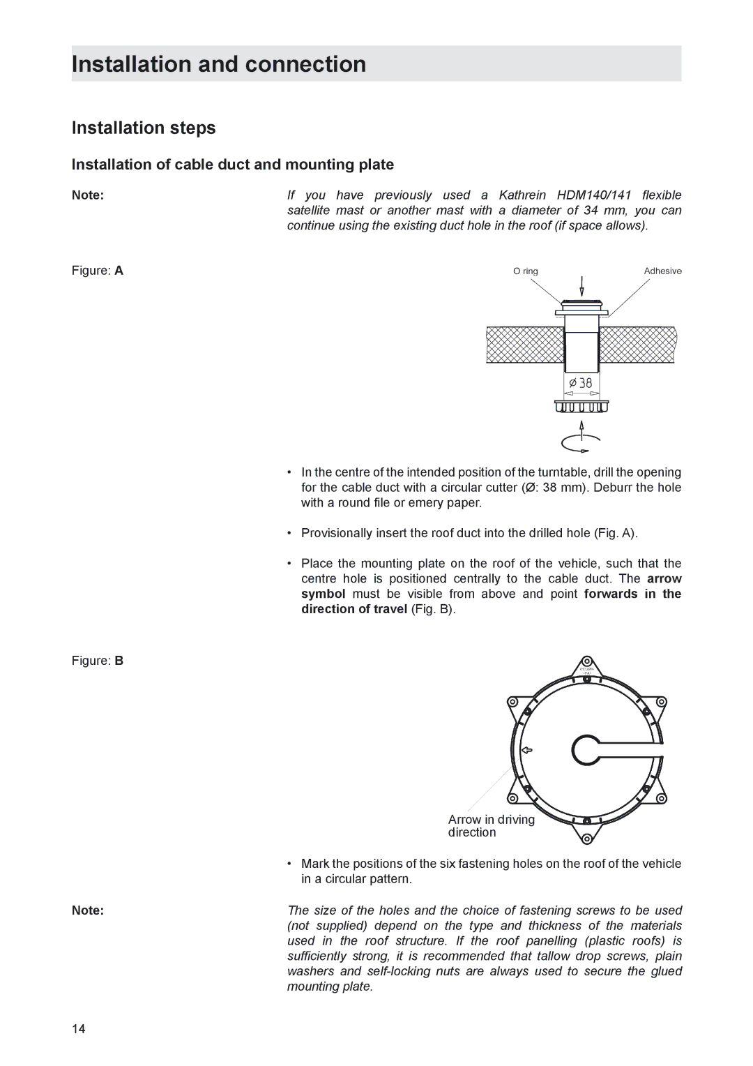
Installation and connection

Only for connection in a motorhome, not in a caravan!

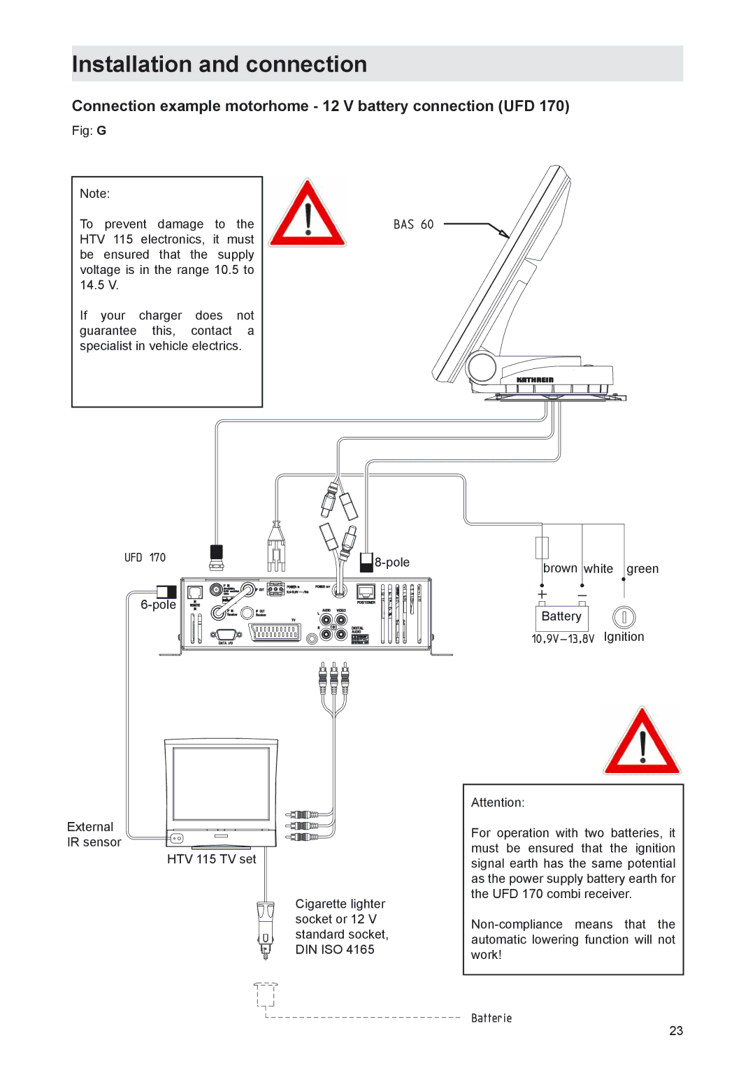
The third, green connecting cable wire, marked “IGNITION” allows you a free choice of connection to a circuit in the vehicle that is activated when the ignition key is turned and then carries a constant 12 V voltage. This type of connection ensures that when the engine is started the antenna is automatically lowered into the park position (the receiver does not need to be turned on).

Check the connections before you re-connect the on-board network.

For commissioning and more detailed information on additional operator functions, we refer you to the separate operating manual enclosed.

Connecting the HTV 115 LCD TV Set

Connect a HTV 115 and the receiver with the included cinch/cinch cable included with the UFD 170.

Make sure that you heed the colour identification of the connectors and outlets on the back side of the receiver.

Connect the TV with the included connection cable for 230V power supply and with the connection cable (identification: HTV 115) for 12 V norm outlets (DIN ISO 4165).

Function information for connection to on-board network

Under certain circumstances, problems can arise when the units are connected to different connecting sockets or circuits/earth potentials. If none are available, it is recommended as depicted in Figure “H” that you connect the connecting sockets for receiver and TV set to the same cable. The current capacity of the circuit used must be checked with respect to the intended application.

For additional information about operating the UFD 170 receiver and the HTV 115, please see the instructions included with the equipment.

Important safety information for CAP 310

The HTV 115 TV set may not be operated while driving or in a moving vehicle (similar to the situation in aircraft, where mobile phones or other electronic devices may not be operated)!

Under unfavourable circumstances, it cannot be completely ruled out that other electronic devices could interfere with the sensitive vehicle electronics and could result in triggering of the airbag, for example.

22
Image 22
Contents MobiSet 2 digital CAP Mobi Set 3 digital CAP Important information about MobiSet 2 digital CAP HTV 115 LCD/TFT television set is only included with the CAPForeign language installation instructions UFD Components of MobiSet 3 digital CAPHDP HTVProduct package Product packageProper use Installation instructionsProper use Intended purposeSafety instructions important notes Safety during installation workSealing glue Proper installation and safetyFundamental information Road Traffic Licensing Regulations StVZOPower supply, fusing Checks before commencing a journeySafety precautions during installation Cleaning the antennaLowering the antenna while driving Safety instructions important notes Required tools and equipment Installation and connectionSelecting the installation location Unpacking and preparationCables may not be cut, as otherwise the proper functioning Installation steps Installation of cable duct and mounting plateInstallation and connection Installation and connection Do not step on the connectors or kink the cables Installation of turntableVersion with cable duct below turntable Fig. E Version with external cable duct Fig. F Brief instructions for installing the HDP Tightening torque 6 NmInstallation of UFD Common interface modules should always be accessibleLaying cables and connecting the turntable HDP Connecting the UFD 170 to the on-board power networkImportant safety information for CAP Connecting the HTV 115 LCD TV SetFunction information for connection to on-board network Connection example motorhome 12 V battery connection UFD Connection example caravan 230 V battery connection UFD Important information for use Safety notesBAS 60 planar antenna BAS 60 with HDPBAS 60 technical data Reception range/footprintPolarisation setting Polarisation settingInstallation process Motorhome/caravan On the turntableView after installation +15 Middle standardDismantling for servicing Address of the service centreElectronic Service Chiemgau GmbH Bahnhofstrasse DismantlingTechnical data Dimensions mmElectric data Sikaflex 291 data sheet Sikaflex 291 technical data sheet Declaration of conformity