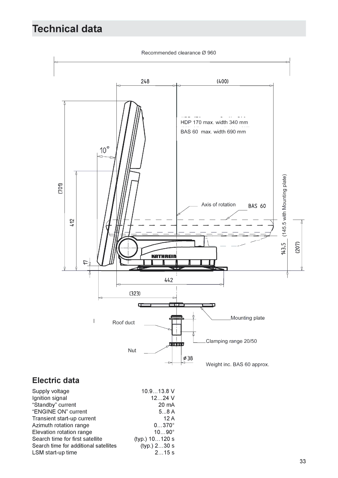
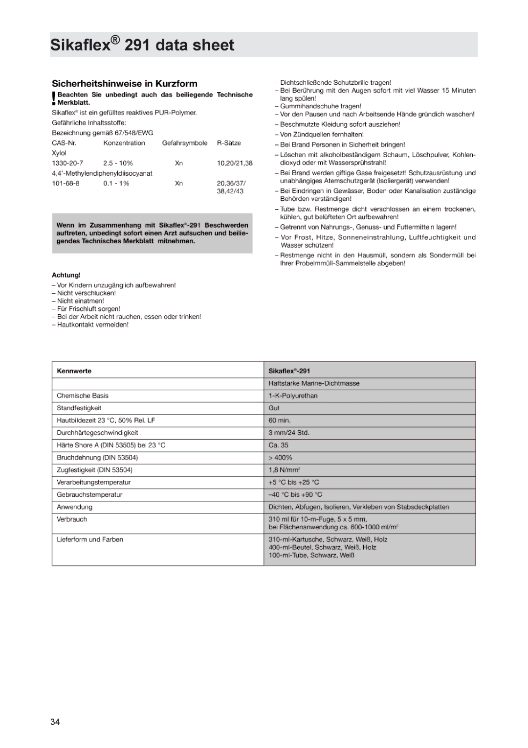
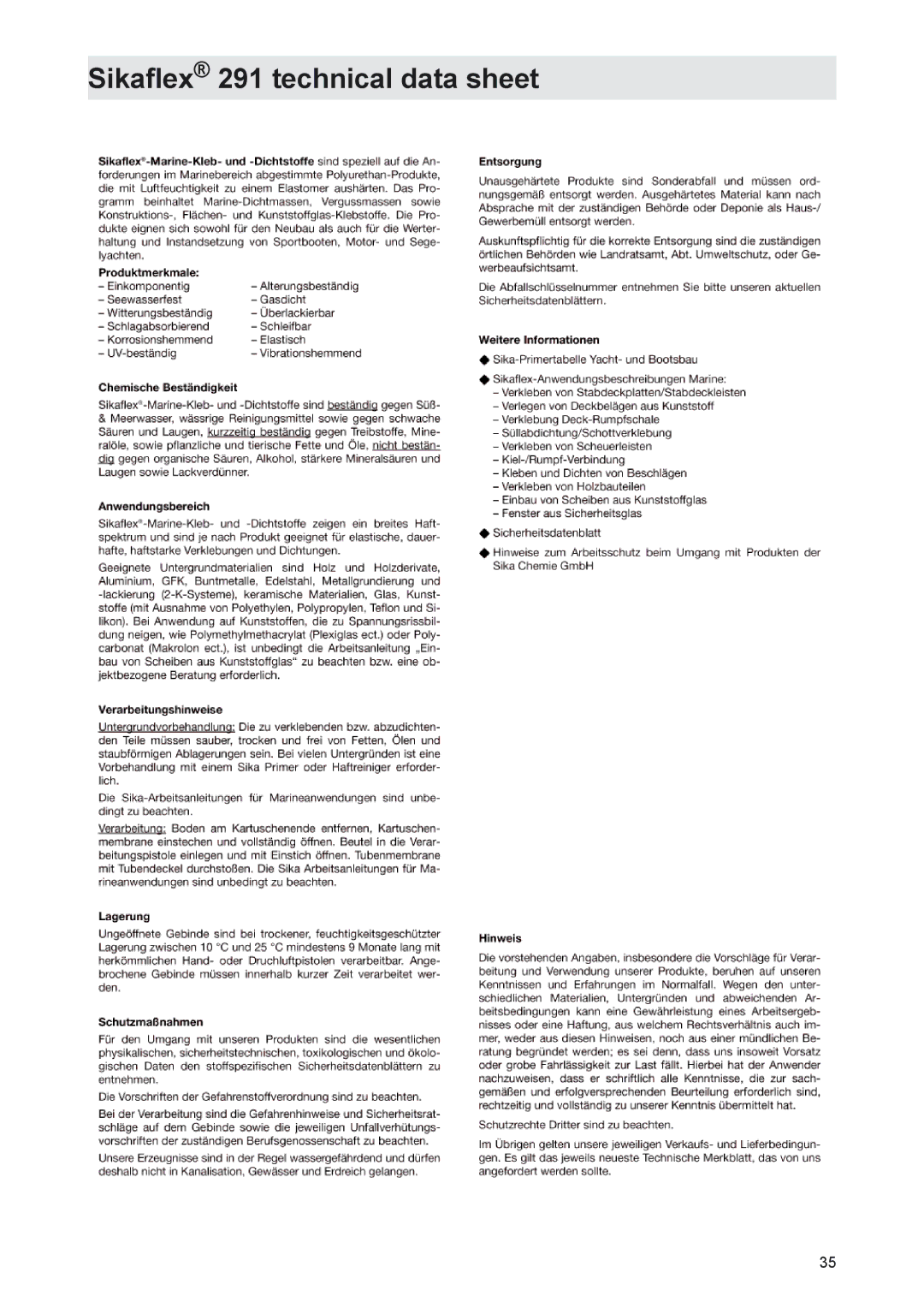
Kathrein MobiSet 3 CAP 310, MobiSet 2 CAP 210 manual Polarisation setting

Page 27

Polarisation setting

Polarisation setting

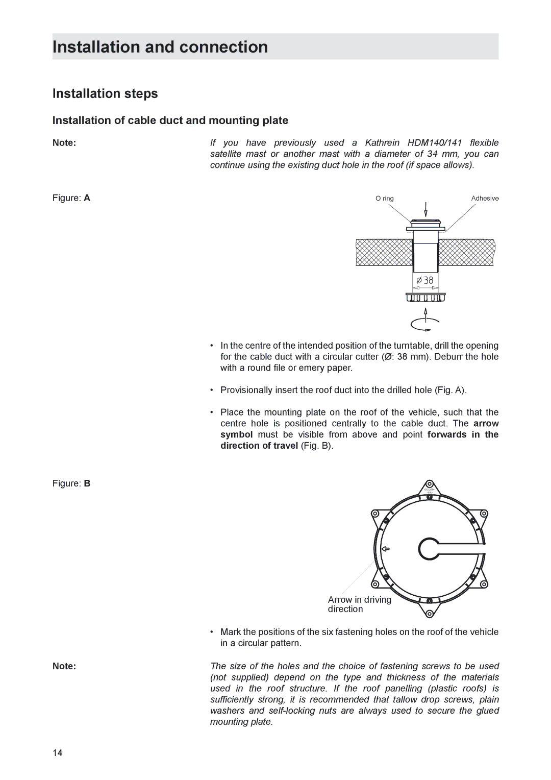
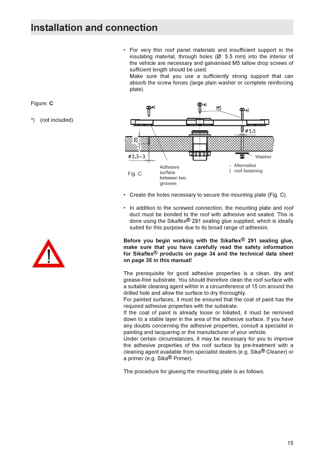
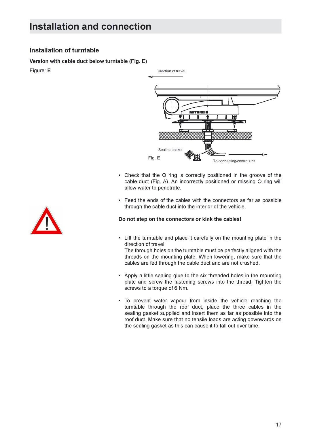
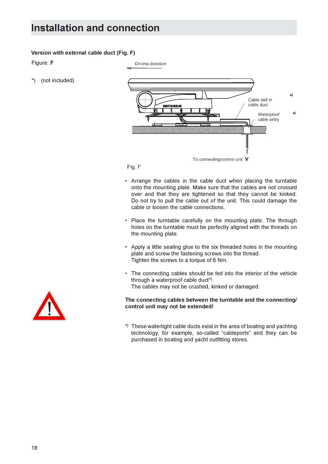
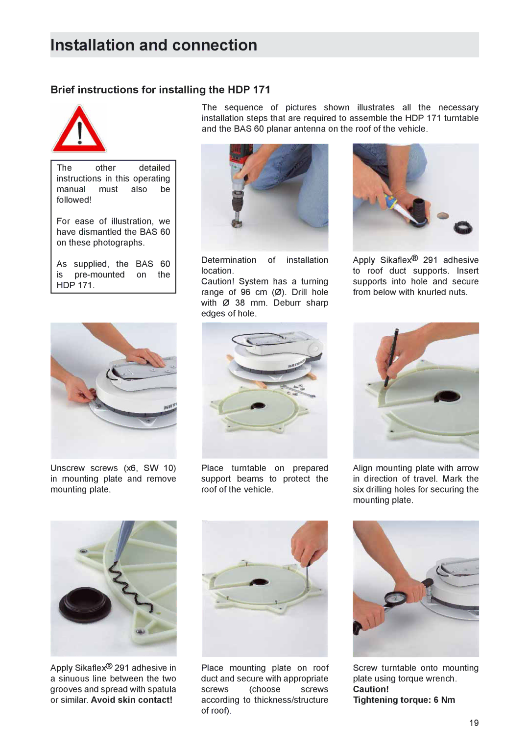
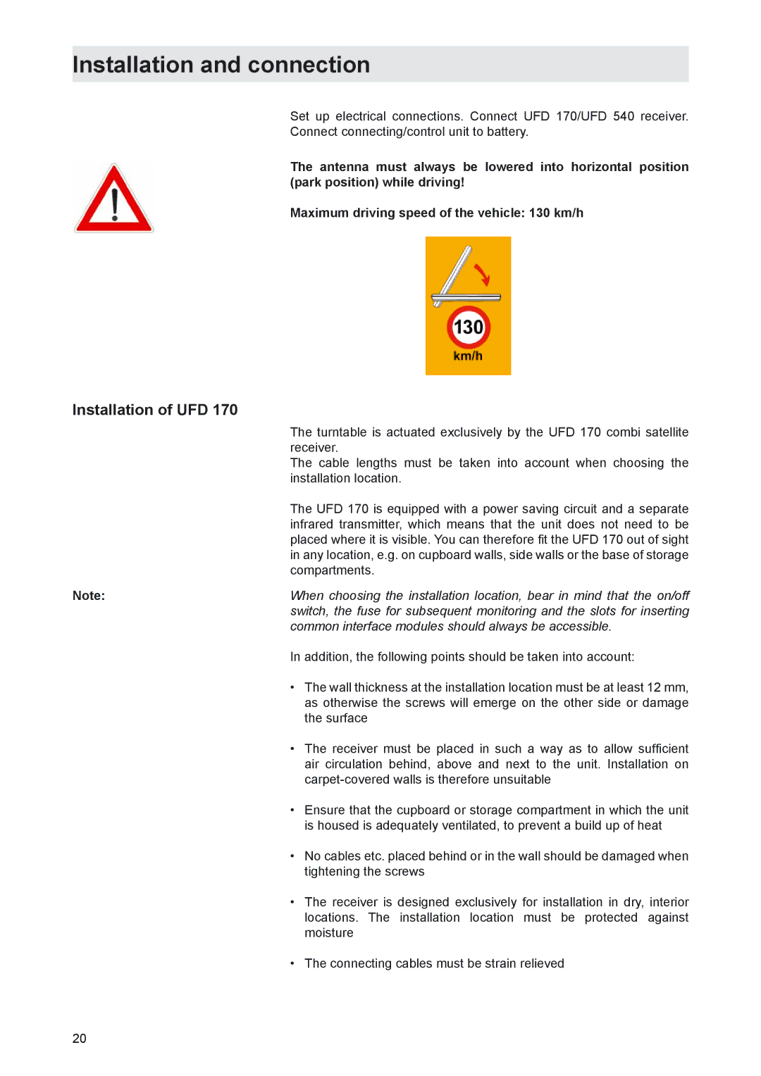
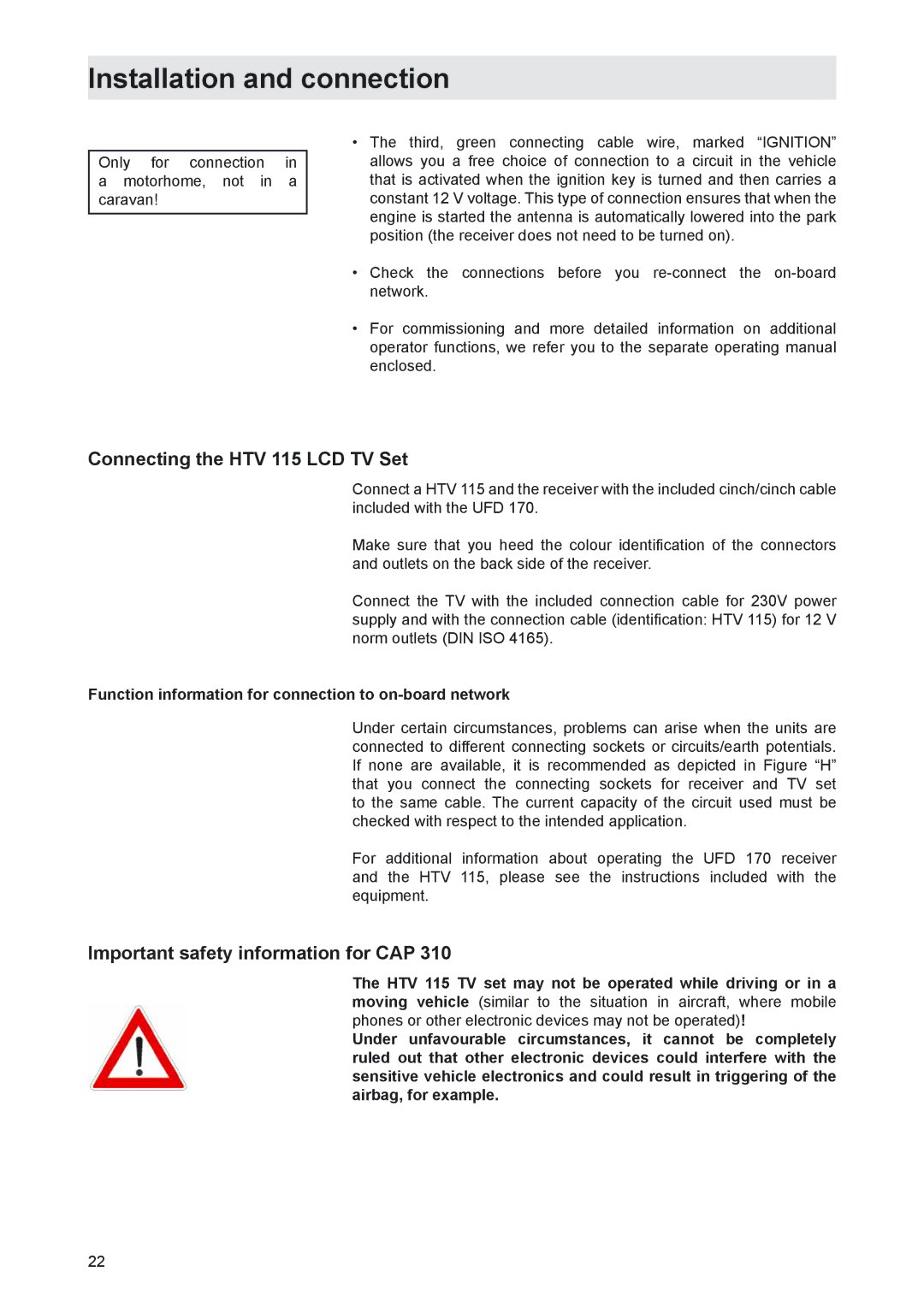
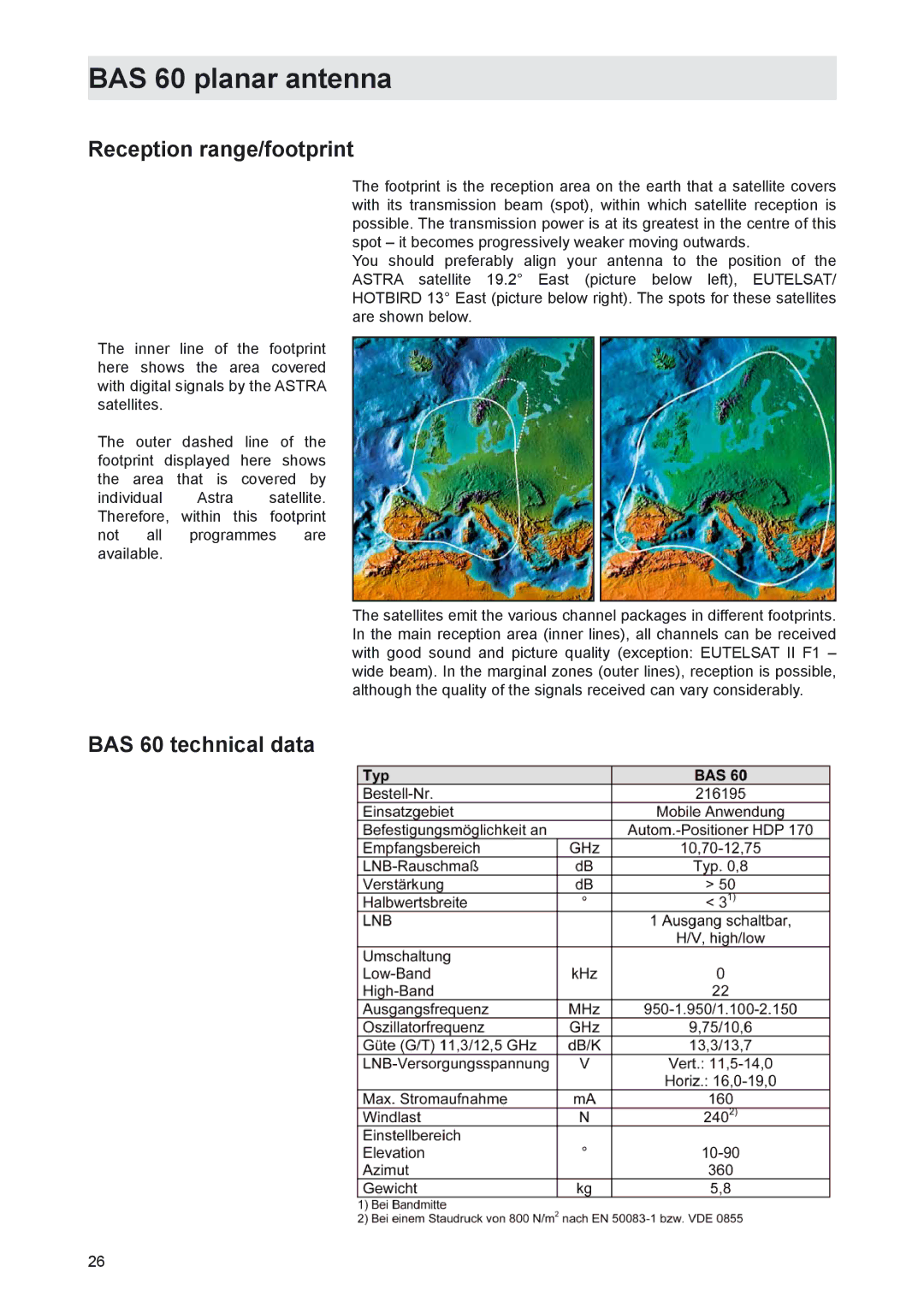
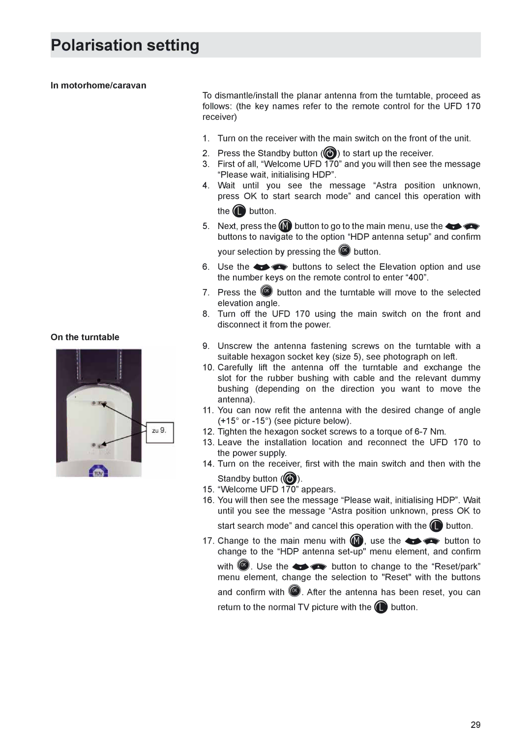
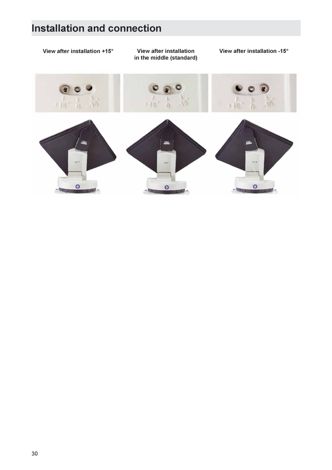
As supplied, the BAS 60 is mounted centrally on the turntable. In this position, you can also receive signals from satellites with deviations in the degree of longitude (of the typical reception range) of between 15° and 20° from the orbit position of the satellite. Deviations in the preferred reception range degree of longitude or more than 15-20° from the orbit position of the satellite allows the BAS 60 polarisation setting to be changed by changing the mounting position.

However, explicit attention is drawn to the fact that positioning the BAS 60 antenna at a deviation of +15° or -15° from the centre position only makes sense if a satellite to the far West or the far East is actually preferred for reception.

+15° if the satellite is more than 15° to 20° to the west of the preferred reception area and -15° if the satellite is more than 15° to 20° to the east of the preferred reception area.

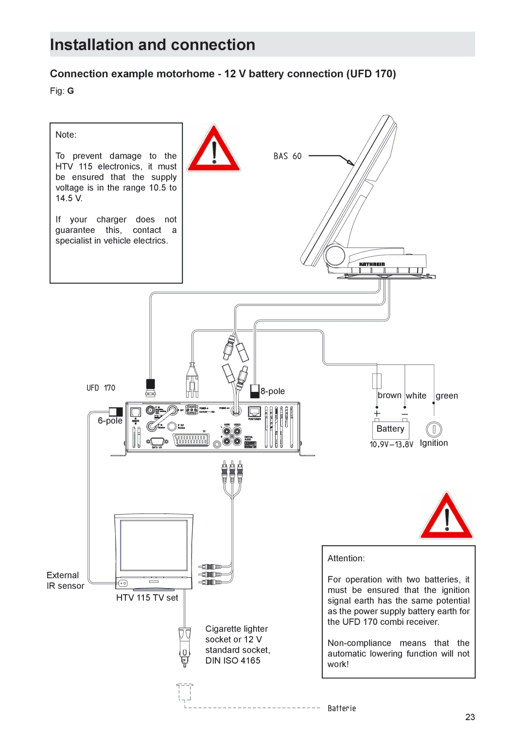
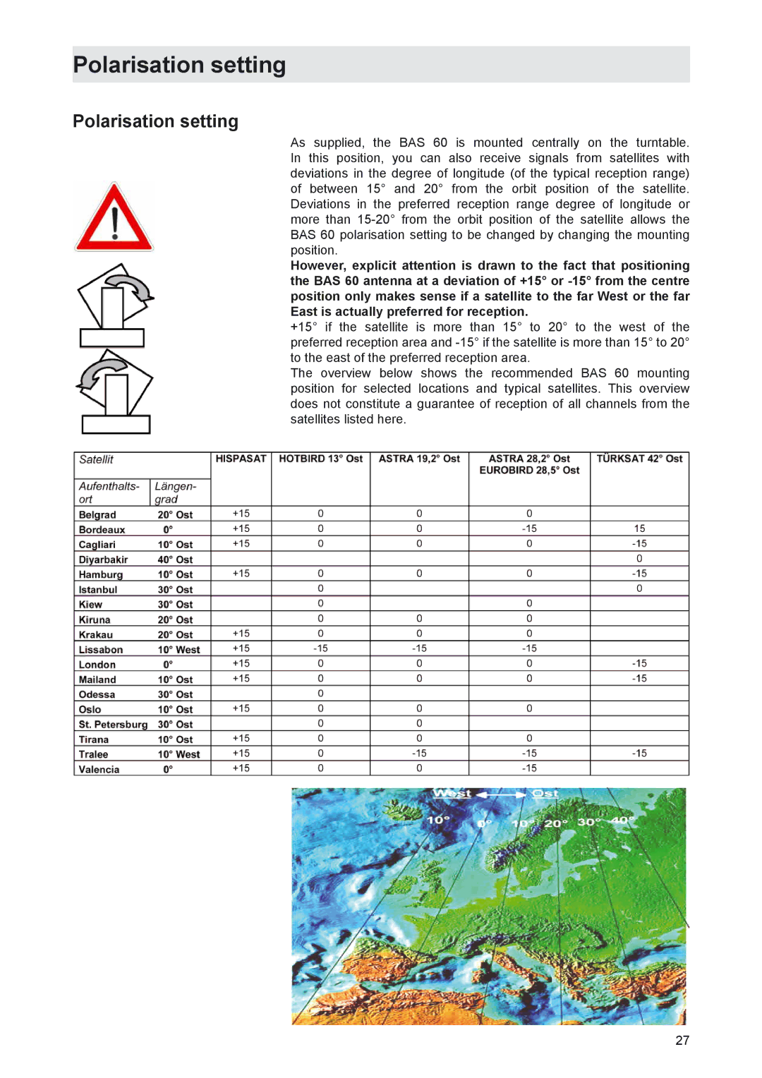
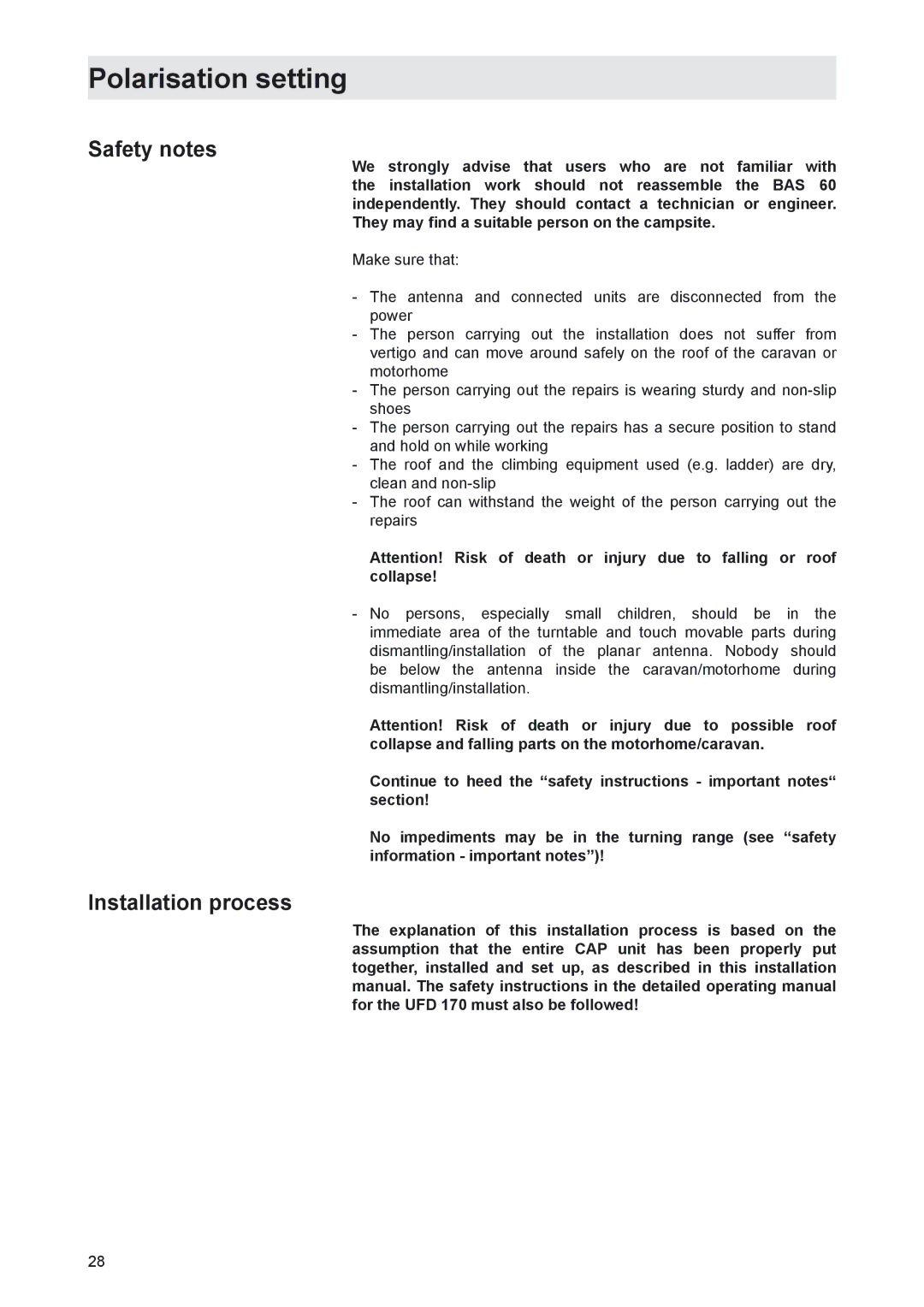
The overview below shows the recommended BAS 60 mounting position for selected locations and typical satellites. This overview does not constitute a guarantee of reception of all channels from the satellites listed here.

27
Image 27
Contents MobiSet 2 digital CAP Mobi Set 3 digital CAP HTV 115 LCD/TFT television set is only included with the CAP Important information about MobiSet 2 digital CAPForeign language installation instructions HTV Components of MobiSet 3 digital CAPHDP UFDProduct package Product packageIntended purpose Installation instructionsProper use Proper useSafety during installation work Safety instructions important notesRoad Traffic Licensing Regulations StVZO Proper installation and safetyFundamental information Sealing glueChecks before commencing a journey Power supply, fusingCleaning the antenna Safety precautions during installationLowering the antenna while driving Safety instructions important notes Unpacking and preparation Installation and connectionSelecting the installation location Required tools and equipmentCables may not be cut, as otherwise the proper functioning Installation of cable duct and mounting plate Installation stepsInstallation and connection Installation and connection Installation of turntable Do not step on the connectors or kink the cablesVersion with cable duct below turntable Fig. E Version with external cable duct Fig. F Tightening torque 6 Nm Brief instructions for installing the HDPCommon interface modules should always be accessible Installation of UFDConnecting the UFD 170 to the on-board power network Laying cables and connecting the turntable HDPConnecting the HTV 115 LCD TV Set Important safety information for CAPFunction information for connection to on-board network Connection example motorhome 12 V battery connection UFD Connection example caravan 230 V battery connection UFD BAS 60 with HDP Safety notesBAS 60 planar antenna Important information for useReception range/footprint BAS 60 technical dataPolarisation setting Polarisation settingInstallation process On the turntable Motorhome/caravanMiddle standard View after installation +15Dismantling Address of the service centreElectronic Service Chiemgau GmbH Bahnhofstrasse Dismantling for servicingDimensions mm Technical dataElectric data Sikaflex 291 data sheet Sikaflex 291 technical data sheet Declaration of conformity