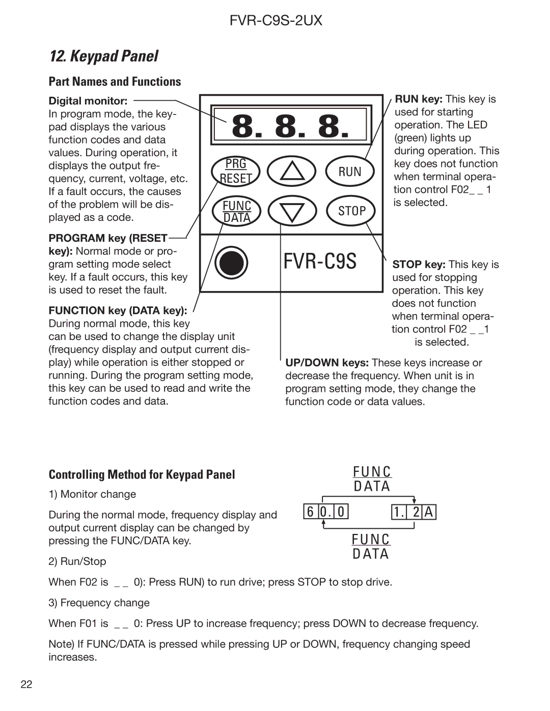
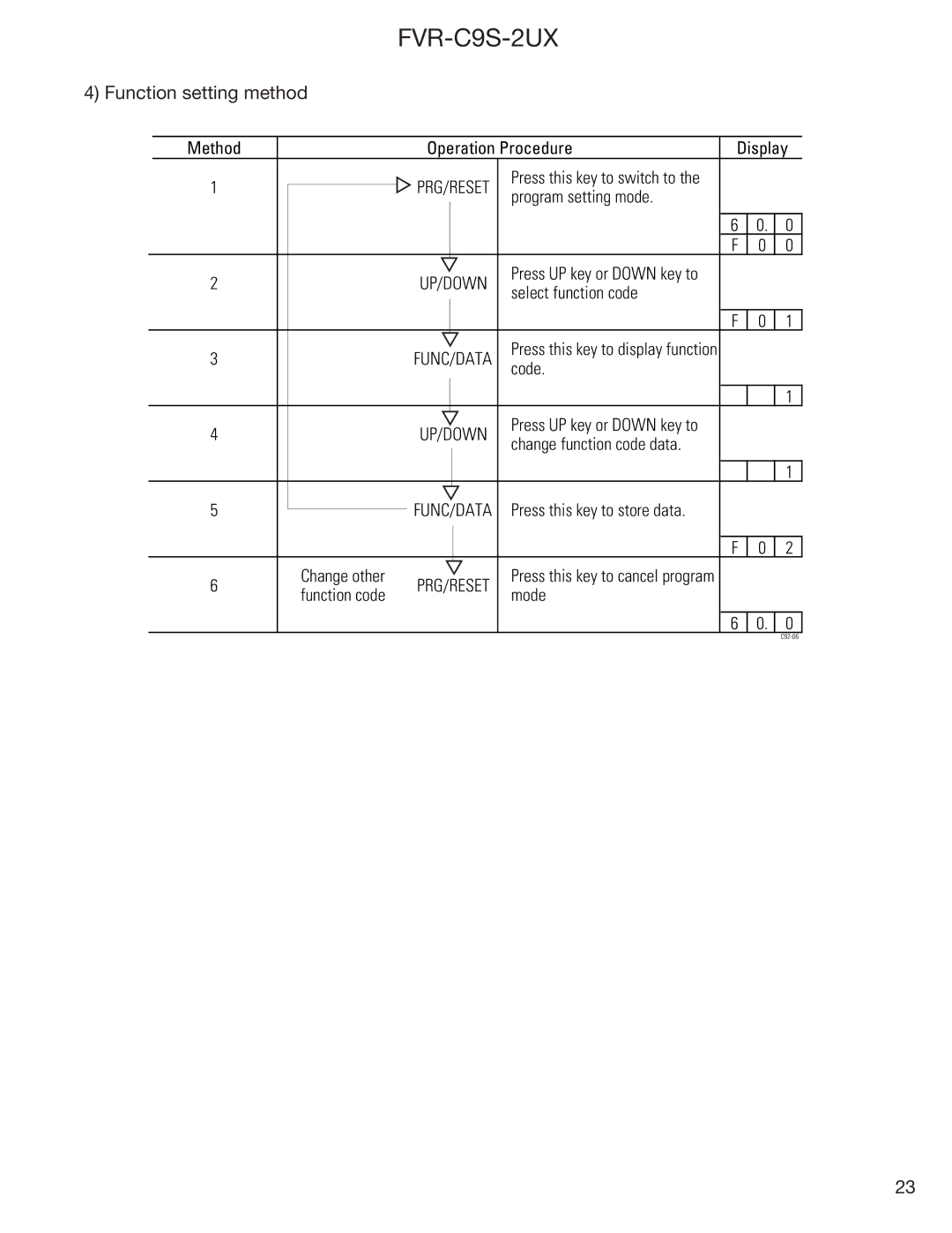
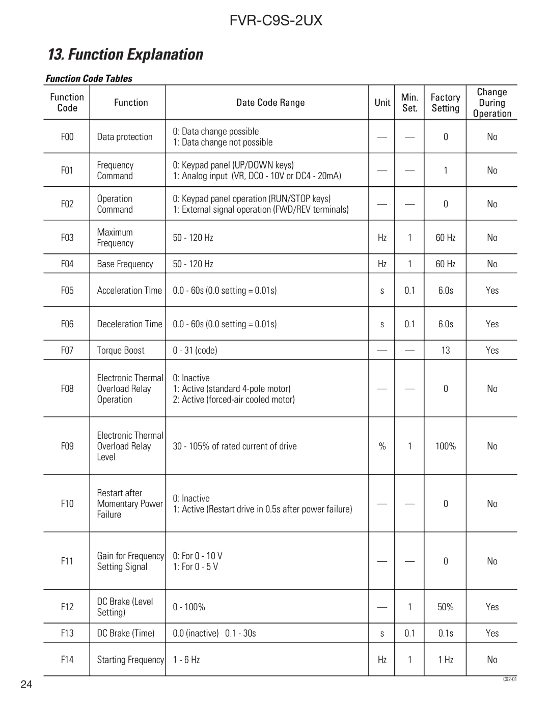
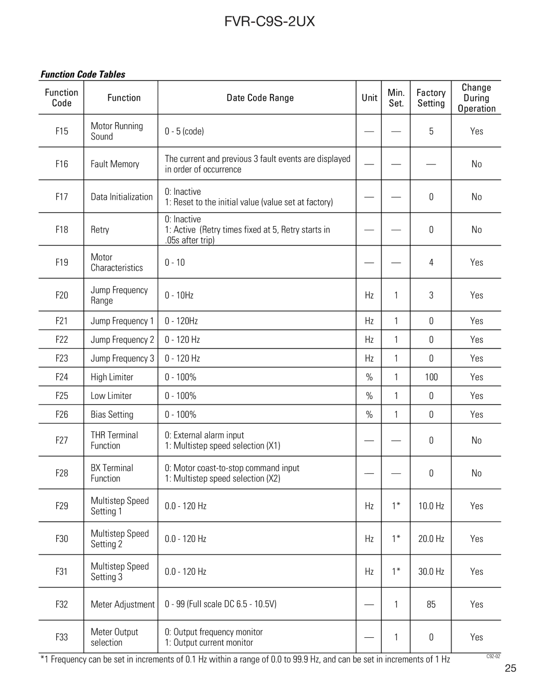
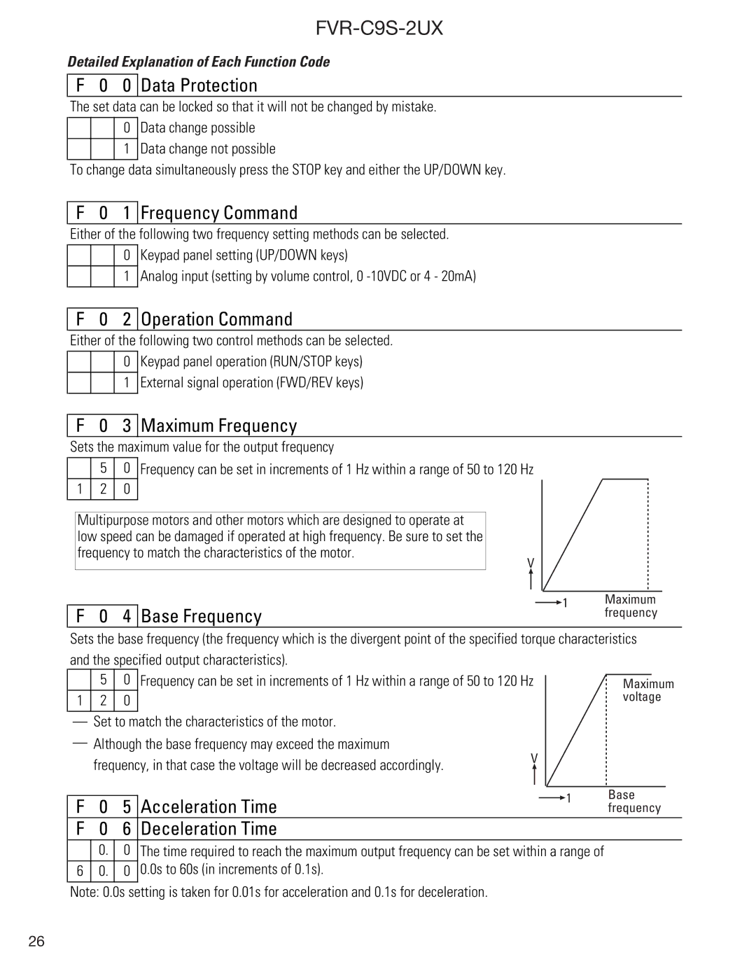
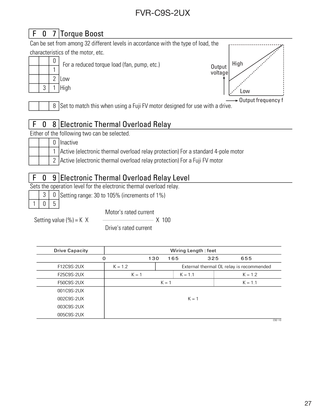
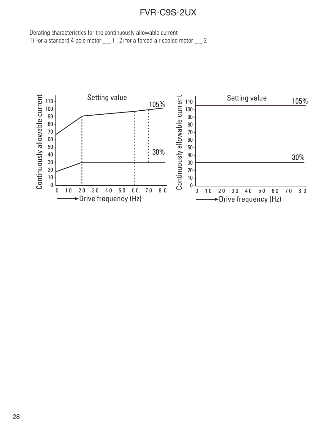
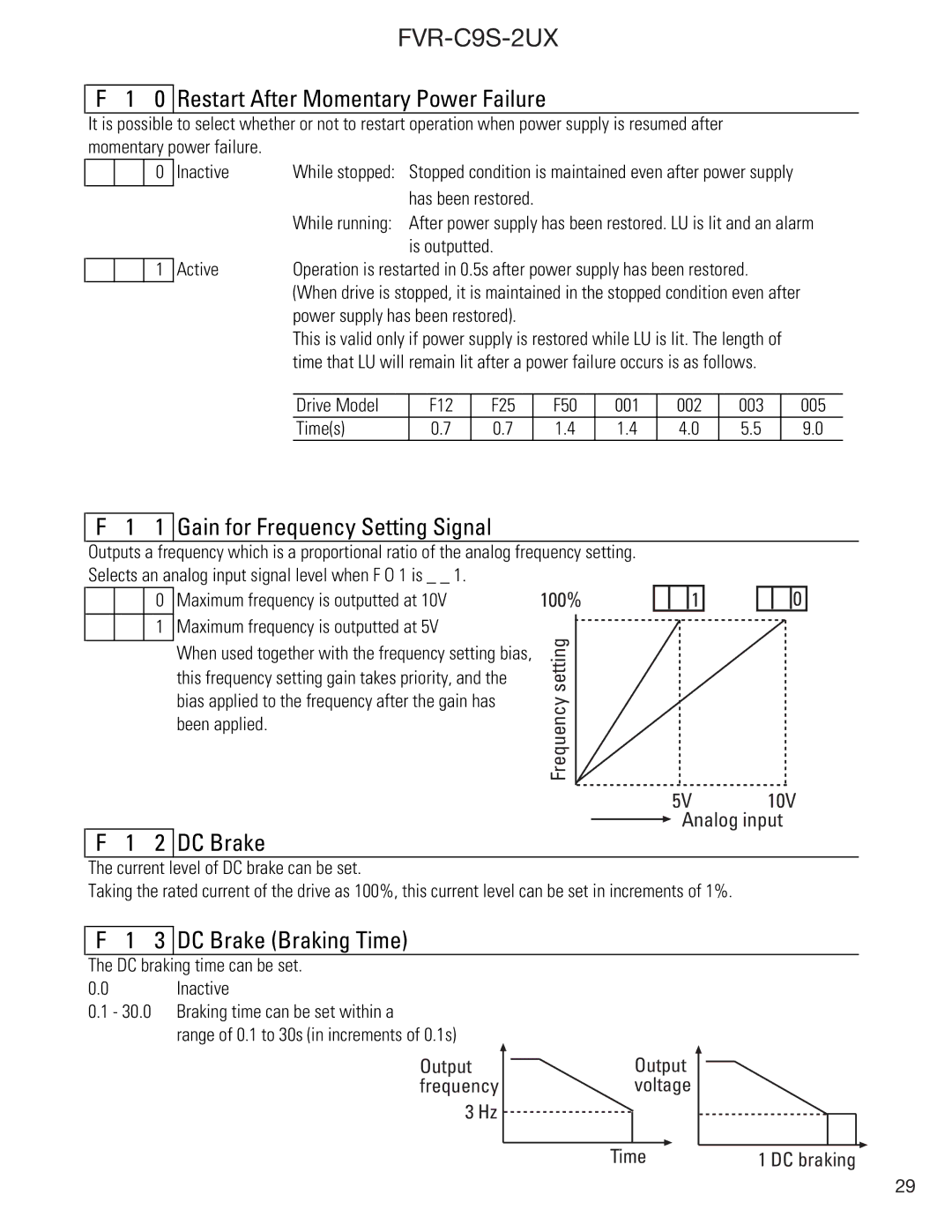
GE FVR-C9S-2UX Drive Series instruction manual External Signal Operation, Fab

Page 16

FVR-C9S-2UX

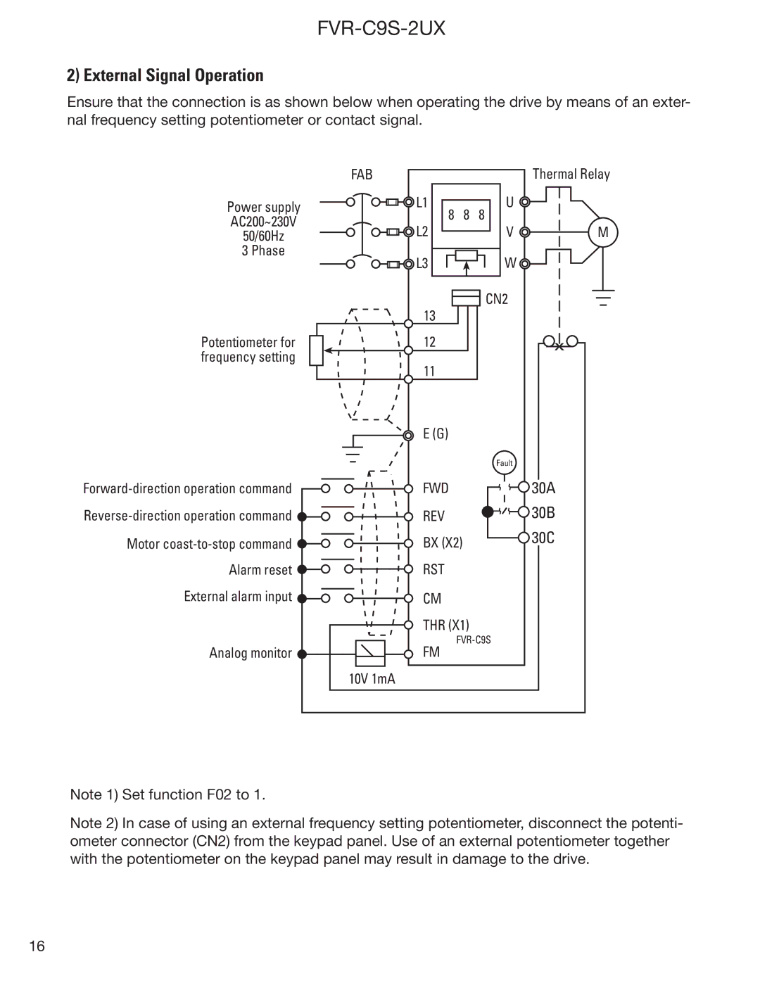
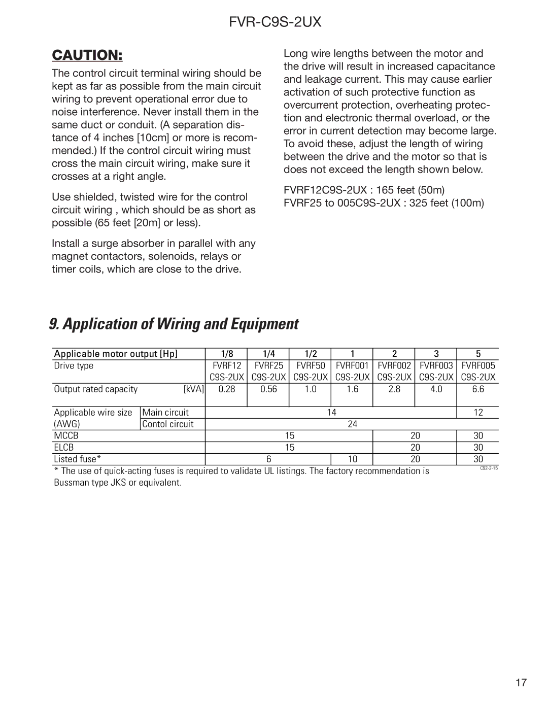
2) External Signal Operation

Ensure that the connection is as shown below when operating the drive by means of an exter- nal frequency setting potentiometer or contact signal.

Power supply

AC200~230V

50/60Hz

3 Phase

FAB

L1

L2

L3

8 8 8

Thermal Relay

U

V M W

Potentiometer for frequency setting

Forward-direction operation command

Reverse-direction operation command

Motor coast-to-stop command

Alarm reset

External alarm input

Analog monitor

Note 1) Set function F02 to 1.

13

CN2


12

x

11


E (G)


Fault

FWD

30A

REV

30B

BX (X2)

30C

RST


CM


THR (X1)


FVR-C9S


FM


10V 1mA

Note 2) In case of using an external frequency setting potentiometer, disconnect the potenti- ometer connector (CN2) from the keypad panel. Use of an external potentiometer together with the potentiometer on the keypad panel may result in damage to the drive.

16
Image 16
Contents FVR-C9S-2UX Drive Series Product specifications are subject to change without notice Contents Safety Precautions Wiring Fire and Electric Shock HazardOperation Electric Shock Hazard Inspection Upon Receipt NameplatePart Names TypeSpecifications Input power Voltage/frequency Supply voltage 3%Type FVR C9S-2UX F12 F25 F50 External Dimensions DWG 1 FVRF12C9S-2UX to FVROO1C9S-2UXDWG 2 FVR002C9S to FVR003C9S-2UX FVR005C9S-2UX Installation Instructions WiringInstallation Conditions Mounting Direction and SpaceDisconnect CRG Lamp 30C Basic Wiring DiagramsKeypad Panel Operation External Signal Operation FABApplication of Wiring and Equipment Applicable motor output Hp Drive typeTerminal Function Explanation Terminal Function ExplanationTerminal Function Explanation Frequency Setting Method OperationPre-Operation Inspection Test Run Check PointsSelecting Operation Method RUN/STOPPart Names and Functions Keypad PanelControlling Method for Keypad Panel Function setting method Function Explanation Function Code TablesMotor Running Code 1 Frequency Command 2 Operation Command0 Data Protection 3 Maximum FrequencyTorque Boost 8 Electronic Thermal Overload RelayElectronic Thermal Overload Relay Level Low High30% 2 DC Brake 1 Gain for Frequency Setting Signal3 DC Brake Braking Time 4 Starting Frequency 6 Fault Memory5 Motor Running Sound 9 Motor Characteristics 7 Data Initialization8 Retry Jump Frequency Range4 High Limiter F 2 5 Low Limiter 6 Bias Frequency7 THR Terminal Function 8 BX Terminal FunctionMultistep Speed Setting 2 Speed Multistep Speed Setting 1 SpeedMultistep Speed Setting 3 Speed 2 FM Terminal Output Level Calibration 3 FM Terminal Function SelectionProtective Functions OC3Warranty Parts and Service Technical Services GE Fuji Drives USA, IncOut-of-Warranty Procedures MotorsIn-Warranty Failure Checklist Latest Fault Previous Faults No MessageFVR-C9S-2UX FVR-C9S-2UX FVR-C9S-2UX