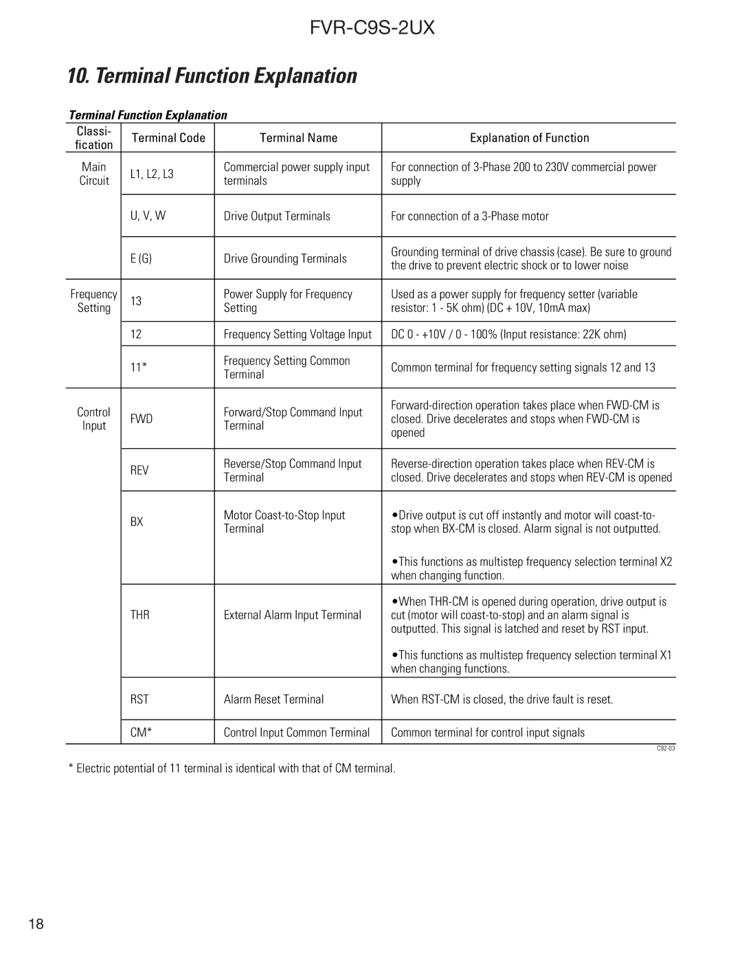
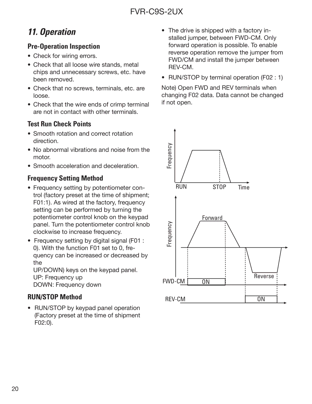
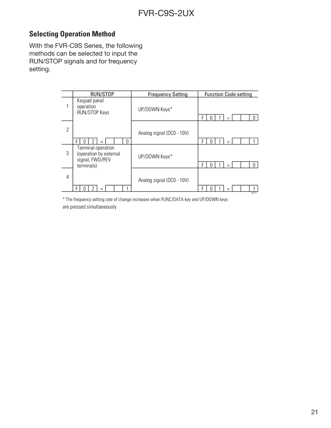
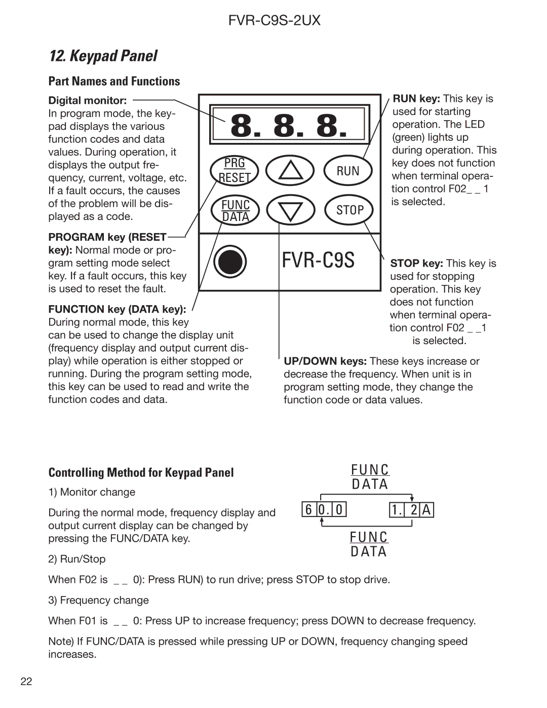
GE FVR-C9S-2UX Drive Series Warranty Parts and Service, Out-of-Warranty Procedures, Motors

Page 36

FVR-C9S-2UX

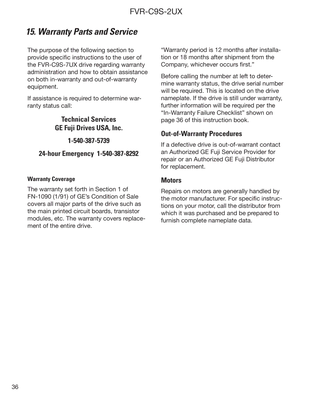
15. Warranty Parts and Service

The purpose of the following section to provide specific instructions to the user of the FVR-C9S-7UX drive regarding warranty administration and how to obtain assistance on both in-warranty and out-of-warranty equipment.

If assistance is required to determine war- ranty status call:

Technical Services

GE Fuji Drives USA, Inc.

1-540-387-5739

24-hour Emergency 1-540-387-8292

Warranty Coverage

The warranty set forth in Section 1 of FN-1090 (1/91) of GE’s Condition of Sale covers all major parts of the drive such as the main printed circuit boards, transistor modules, etc. The warranty covers replace- ment of the entire drive.

“Warranty period is 12 months after installa- tion or 18 months after shipment from the Company, whichever occurs first.”

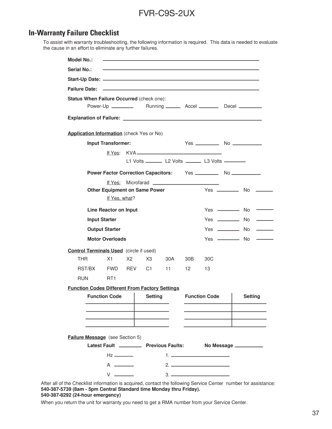
Before calling the number at left to deter- mine warranty status, the drive serial number will be required. This is located on the drive nameplate. If the drive is still under warranty, further information will be required per the “In-Warranty Failure Checklist” shown on page 36 of this instruction book.

Out-of-Warranty Procedures

If a defective drive is out-of-warrant contact an Authorized GE Fuji Service Provider for repair or an Authorized GE Fuji Distributor for replacement.

Motors

Repairs on motors are generally handled by the motor manufacturer. For specific instruc- tions on your motor, call the distributor from which it was purchased and be prepared to furnish complete nameplate data.

36
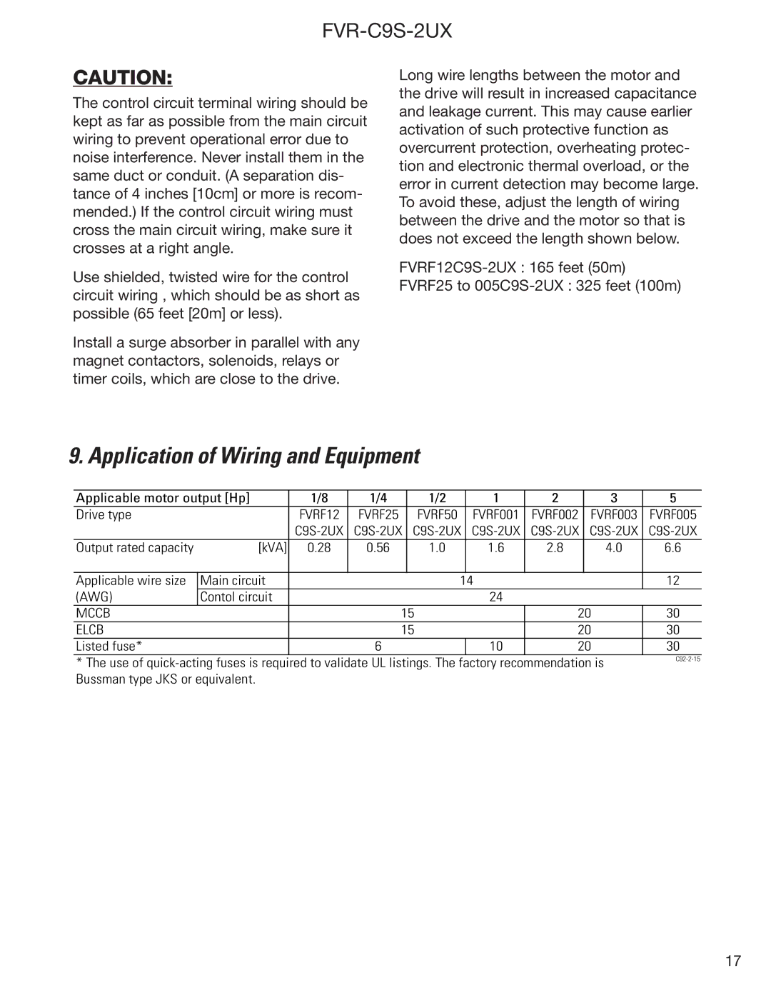
Image 36
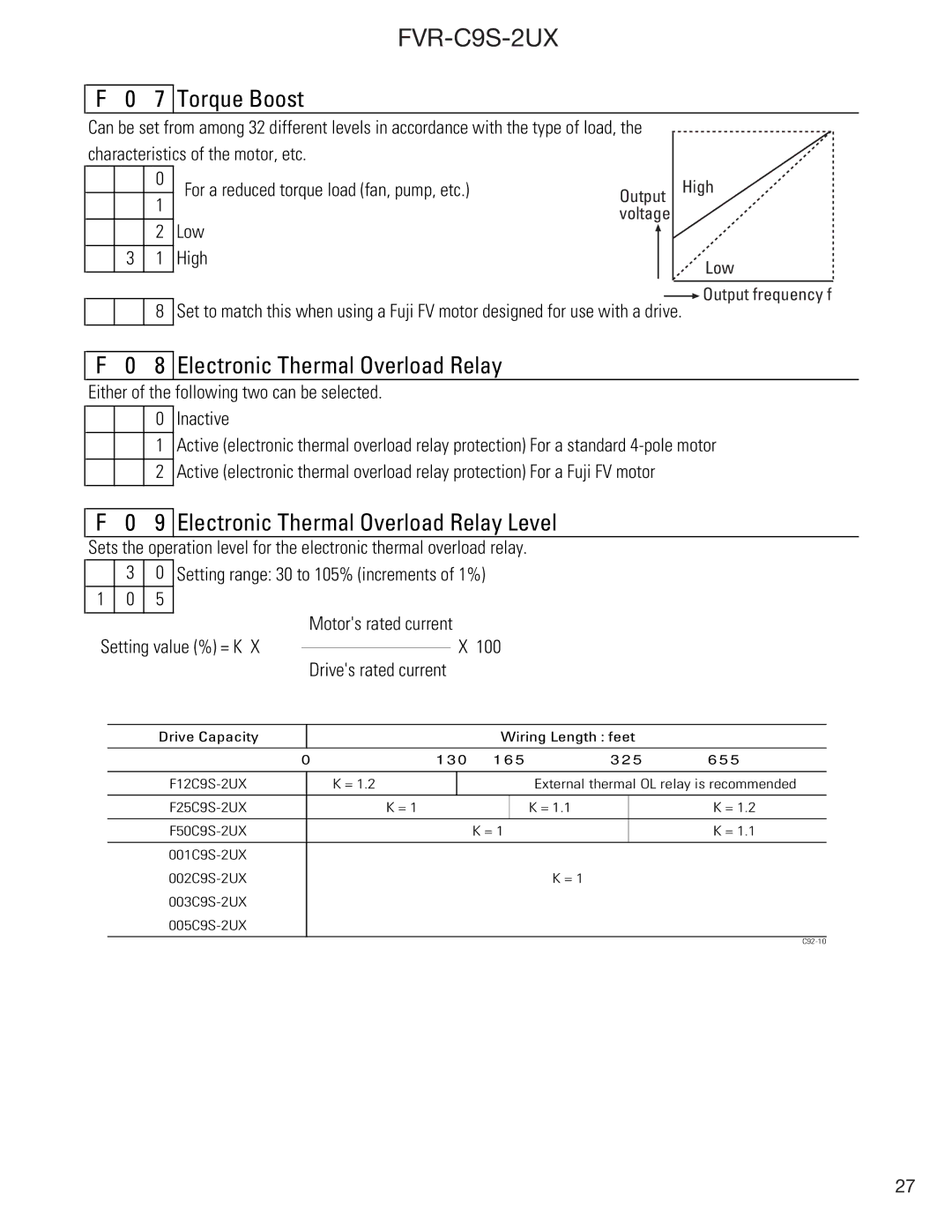
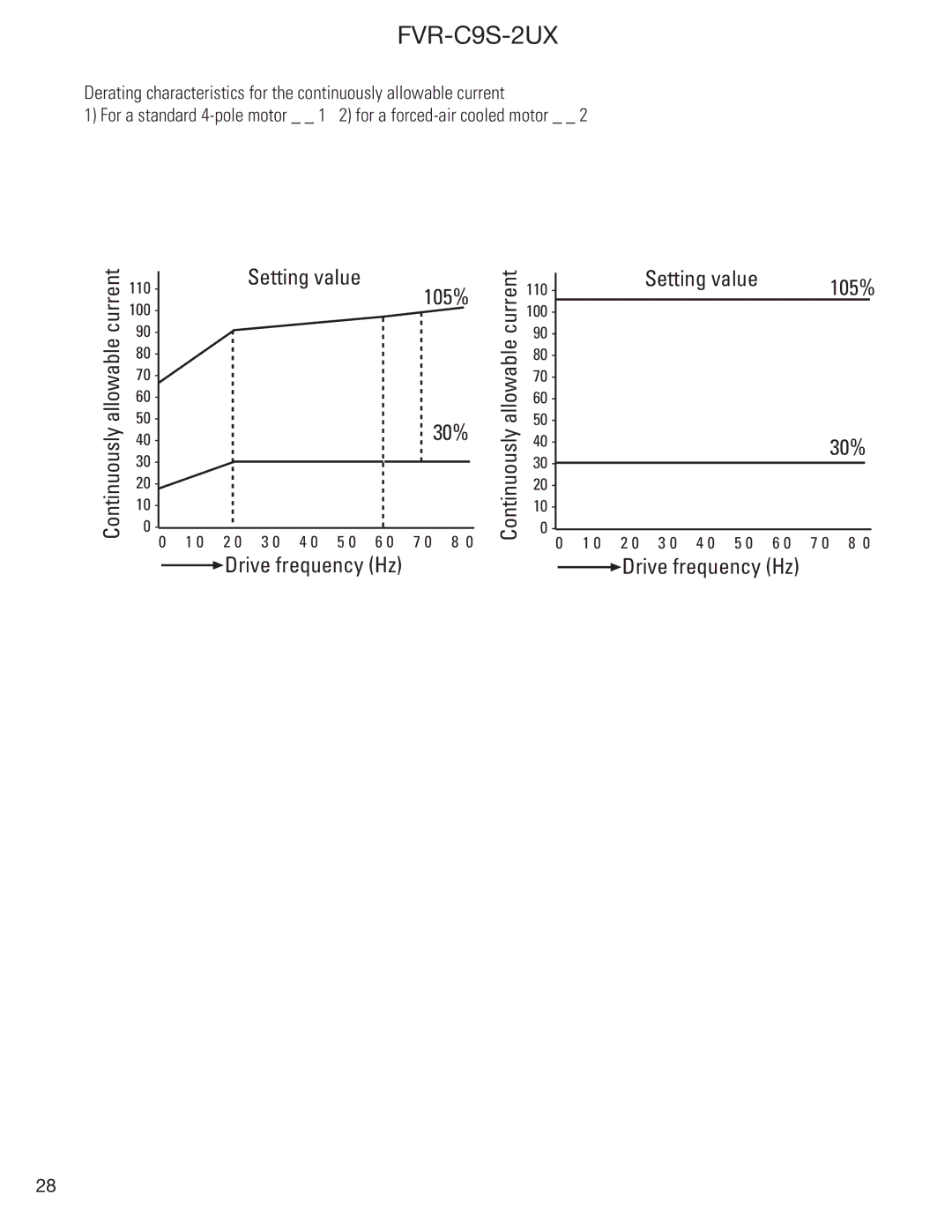
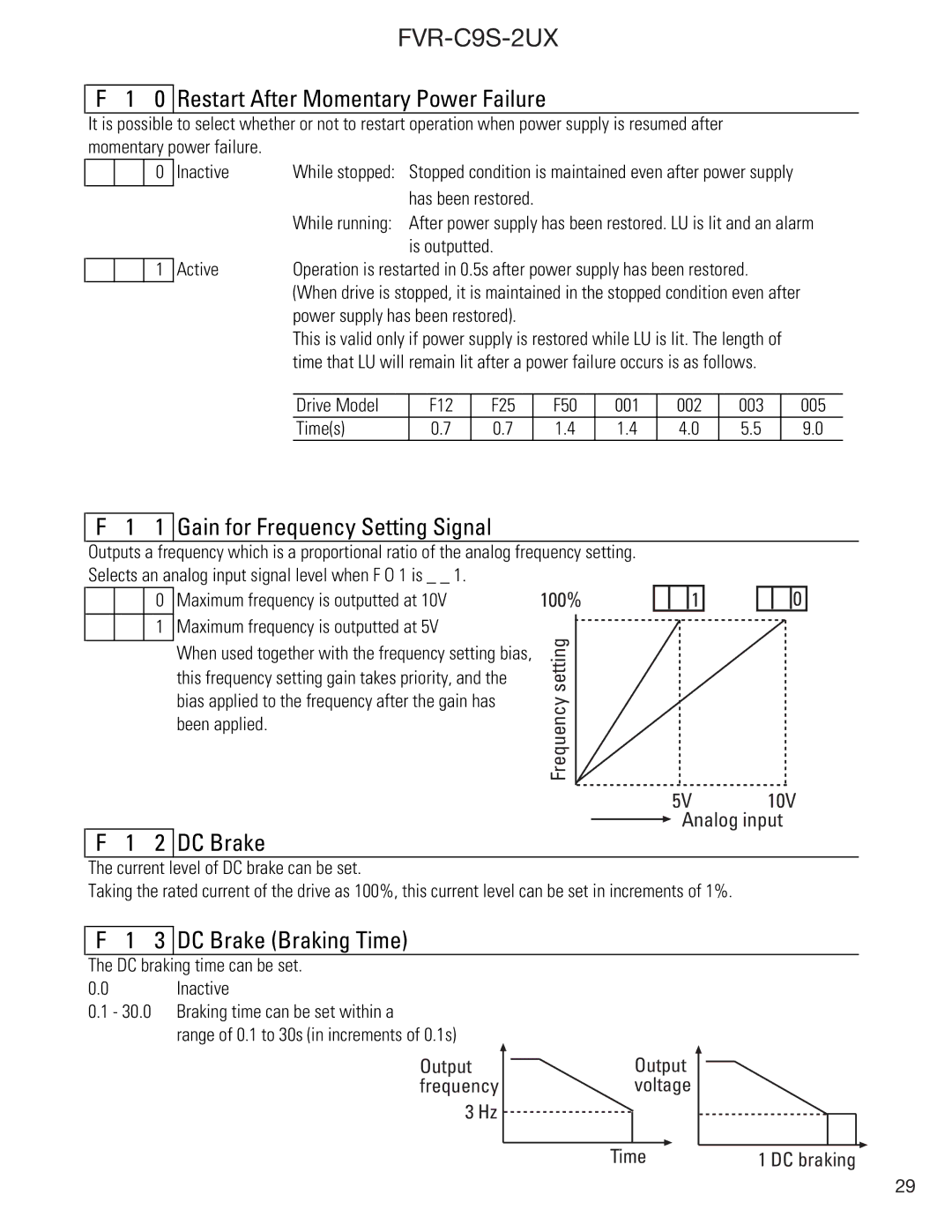
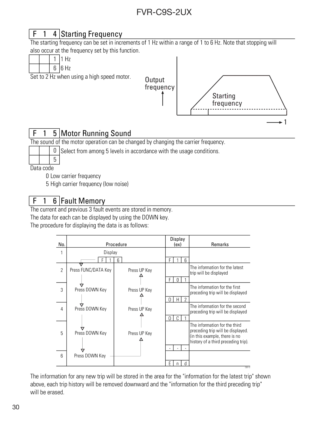
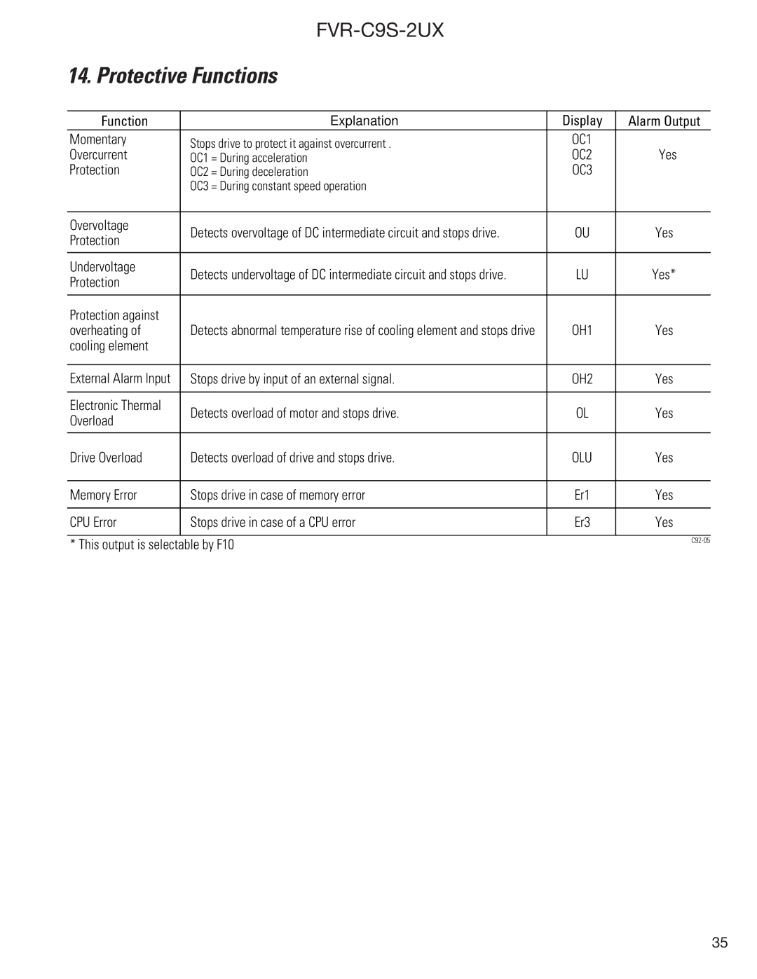
Contents FVR-C9S-2UX Drive Series Product specifications are subject to change without notice Contents Safety Precautions Wiring Fire and Electric Shock HazardOperation Electric Shock Hazard Inspection Upon Receipt NameplatePart Names TypeSpecifications Input power Voltage/frequency Supply voltage 3%Type FVR C9S-2UX F12 F25 F50 External Dimensions DWG 1 FVRF12C9S-2UX to FVROO1C9S-2UXDWG 2 FVR002C9S to FVR003C9S-2UX FVR005C9S-2UX Installation Instructions WiringInstallation Conditions Mounting Direction and SpaceDisconnect CRG Lamp Basic Wiring Diagrams 30CKeypad Panel Operation External Signal Operation FABApplication of Wiring and Equipment Applicable motor output Hp Drive typeTerminal Function Explanation Terminal Function ExplanationTerminal Function Explanation Frequency Setting Method OperationPre-Operation Inspection Test Run Check PointsSelecting Operation Method RUN/STOPKeypad Panel Part Names and FunctionsControlling Method for Keypad Panel Function setting method Function Explanation Function Code TablesMotor Running Code 1 Frequency Command 2 Operation Command0 Data Protection 3 Maximum FrequencyTorque Boost 8 Electronic Thermal Overload RelayElectronic Thermal Overload Relay Level Low High30% 1 Gain for Frequency Setting Signal 2 DC Brake3 DC Brake Braking Time 6 Fault Memory 4 Starting Frequency5 Motor Running Sound 9 Motor Characteristics 7 Data Initialization8 Retry Jump Frequency Range4 High Limiter F 2 5 Low Limiter 6 Bias Frequency7 THR Terminal Function 8 BX Terminal FunctionMultistep Speed Setting 1 Speed Multistep Speed Setting 2 SpeedMultistep Speed Setting 3 Speed 2 FM Terminal Output Level Calibration 3 FM Terminal Function SelectionProtective Functions OC3Warranty Parts and Service Technical Services GE Fuji Drives USA, IncOut-of-Warranty Procedures MotorsIn-Warranty Failure Checklist Latest Fault Previous Faults No MessageFVR-C9S-2UX FVR-C9S-2UX FVR-C9S-2UX