Yamaha RX-V496RDS Receiving RDS Stations, Description of RDS Data, Changing the RDS Mode

Page 34

RECEIVING RDS STATIONS

Radio Data System (RDS) is a data transmission system by FM stations in many countries. Stations using this system transmit an inaudible stream of data in addition to the normal radio signal.

RDS data contains various information such as PI (Program Identification), PS (Program Service name), PTY (Program Type), RT (Radio Text), CT (Clock Time), EON (Enhanced Other Networks), etc. The RDS function is carried out among the network stations.

Description of RDS Data

This unit can receive PI, PS, PTY, RT, CT, and EON data when receiving RDS broadcasting stations.

PS (Program Service name) mode:

The name of the RDS station being received is displayed.

PTY (Program Type) mode:

The program type on the RDS station being received is displayed. There are 15 program types to classify RDS stations. You can make this unit search for a station which is broadcasting a program of the desired type. Refer to page 33 for details.

RT (Radio Text) mode:

Information about the program (such as the title of the song, name of the singer, etc.) on the RDS station being received is displayed by a maximum of 64 alphanumeric characters, including the umlaut symbol. If other characters are used for RT data, they are displayed with under-bars.

CT (Clock Time) mode:

The current time is displayed and updated every minute. If the data are accidentally cut off, “CT WAIT” may appear.

EON (Enhanced Other Networks):

Refer to page 34.

Changing the RDS Mode

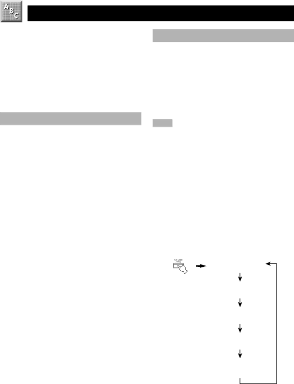
The four modes are available in this unit for displaying RDS data. When an RDS station is being received, PS, PTY, RT and/or CT that correspond to the RDS data services offered by the station light up on the display. Press RDS MODE/ FREQ repeatedly to change the display mode among the RDS data offered by the transmitting station in the order shown below. Illumination of the red indicator next to the RDS mode indicator shows that the corresponding RDS mode is now selected.

Notes

When an RDS station is being received, do not press RDS MODE/FREQ until one or more RDS mode indicators light up on the display. If you press the button before the indicators light up on the display, the mode cannot be changed. This is because the unit has not yet received all of the RDS data on the station.

RDS data not offered by the station cannot be selected.

The RDS data service cannot be utilized by this unit if the received signal is not strong enough. In particular, the RT mode requires a large amount of data to be received, so it is possible that the RT mode may not be displayed even if other RDS modes (PS, PTY, etc.) are displayed.

RDS data cannot sometimes be receive under poor reception conditions. If so, press TUNING MODE so that the “AUTO” indicator goes off from the display. Although the reception mode is changed to monaural by this operation, when you change the display to RDS mode, RDS data may be displayed.

If the signal strength is weakened by external interference during the reception of an RDS station, the RDS data service may be cut off suddenly and “...WAIT” will appear on the display.

PS mode

PTY mode

RT mode

CT mode

Frequency

display mode

32

Image 34
Contents RX-V496RDS For U.K. customers Special Instructions for U.K. ModelFeaturescontents Getting Started Checking the Package ContentsBattery Replacement ControlUsing the Remote Control Controls and Functions Front PanelTuning Mode AUTO/MAN’L Mono PRESET/TUNINGPRESET/TUNING, Edit PTY Seek ModeDisplay Remote Control Speaker Placement Speaker SetupSpeakers to Be Used Before Connecting Components ConnectionsIndoor FM antenna included Connecting the AntennasOutdoor FM antenna Outdoor AM antenna Connecting the AM loop antennaAM loop antenna included Ground GND terminalConnecting an Audio Component Phono terminalsVideo signal terminals Connecting a Video ComponentAudio signal terminals Digital audio signal terminalsVideo terminals Video AUX terminals on the front panelRear speaker terminals Connecting SpeakersMain speaker terminals Center speaker terminalConnecting to the Rear and Center Speakers terminals Connecting to the Main Speakers terminalsSpeaker cables Connecting the Power Supply Cords Impedance Selector SwitchAC Outlets Switched Turn up the volume Adjusting the Speaker BalanceBefore You Start Adjusting Using the Test Tone Set BASS, Treble and Balance to the 0 position Press TestWhen the adjustment is complete, press Test Test OFF appears on the display and the test tone stopsPress Speakers a or B Playing a SourceTo select a tape or an MD source To select the mainTo mute the sound When you have finished using this unitBGV background video function DTS Switching the input modeAuto AnalogEncoded with DTS Selecting a DSP Program On the remote controlDigital Sound Field Processor DSP Effect Off the effect speakersSound Field Program Dgtl Spectacle Program Subprogram Features MovieTheater Dgtl AdventureDolby Pro Logic + 2 digital sound fields For Hi-Fi audio sourcesDolby Digital or DTS + 3 digital sound fields Manual Tuning TuningAutomatic Tuning Press PRESET/TUNING Edit to turn z offStations only Automatic preset tuning optionsWhen automatic preset tuning is completed Hold down Memory for about three secondsManual Preset Tuning To Recall a Preset StationRecall preset station E1 Exchanging Preset StationsExample If you want to exchange preset station E1 with A5 Hold down PRESET/TUNING Edit for about three secondReceiving RDS Stations Changing the RDS ModeDescription of RDS Data Press PTY Seek Mode to set the unit in the PTY Seek mode To cancel this functionProgram types in the PTY mode PTY Seek FunctionMake sure that the EON indicator lights up on the display EON FunctionRecording a Source on TAPE, MD or Video Cassette Select the source you want to recordCenter SP Rear SP Main SP Bass OUT Main LVL Range DTS LFE Cntr Delay 10.MEM. Guard 11.SAT InputSET Menu D. LFEDescription of Each Item Center SPMAX Range Adjusting the dynamic rangeMIN Auto Cntr Delay Adjusting the delay of the center soundLast Sound Output Level of the Center Delay Time and Speaker Output LevelsDelay Time SubwooferAdjusting Method Canceling the Selected Sleep Timer Sleep TimerSetting the Sleep Timer Controlling the Components Connected to This Unit Preset Remote ControlExample To control Yamaha CD player TAPE/MD Mode Description of Each ModeDisplay MD CD Mode DisplayDVD/LD Mode DVD Menu ModeCBL/SAT Mode VCR ModeTV Mode Advanced Information Setup codesTo use a second and third VCR Returning to the factory-set codes Enter the code numberSymptom Cause Remedy TroubleshootingGeneral Tuner Be heardWhen playing back a source encoded with DTS Remote controlOthers Specifications Glossary Cinema DSP Cinema DSPIndex Video components DVD/LD player, VCR and TVBSR SEG Satellite Tuner CableVCR LD Player DVD PlayerCD Player MD Recorder Tape DeckV502870-2 Quick Reference Card Amptuner TAPE/MD DVD/LDDVD Menu VCR CBL/SAT VCR Stop