JVC TK-C1430 manual Manual Adjustment of White Balance

Page 37

Manual Adjustment of White Balance

When automatic adjustment of the white balance results in a “reddish screen”, etc., adjust the white balance manually.

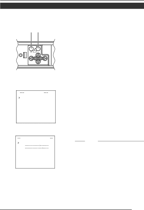
MENU button SET button

SET


CAMERA

AWC

SETUP


MENU


V I DE O ADJ U ST


WH I T E

BA L ANCE

AWC

C OLOUR

L E V E L

NORMAL

E NHA NCE L E V E L

NORMAL

P E DE ST AL LE V E L

NORMAL

A UT O BL AC K CT L

OF F

VIDEO ADJUST screen

WH I T E BALAN C E CONT RO L

AWC

SE T . .


R :

:

B

M g :

:

G

WHITE BALANCE

CONTROL screen

1. Set the WHITE BALANCE item on the VIDEO ADJUST screen to AWC and press the SET button.

*The WHITE BALANCE adjustment screen appears on the monitor.

*Select AWC SET, and press the SET button. AWC (white balance adjust- ment) is performed, and the WHITE BALANCE CONTROL screen appears on the monitor.

2.Select the hue to be adjusted. (R/B or

Mg/G)

Press the or button.

3.Adjust the hue.

Press the or button.

*The “ ı ” indicator moves in accordance with the setting. When a setting is changed, the “+” mark appears at the original position.

4.Concluding manual white balance ad- justment.

Pushing the MENU button returns the screen to VIDEO ADJUST.

MEMO

If the mode is changed from color to black- and-white during the color phase adjustment on the WHITE BALANCE CONTROL screen, the VIDEO ADJUST screen will be brought back. At this time, any adjusted value will not be saved.

E-37

Image 37
Contents TK-C1430 Important Safeguards Page Safety Precautions Contents Memo FeaturesReference page or item Operating Precautions Lens mount Controls, Connectors and IndicatorsCamera-mounting screw Hole 1/4 inch Rotation-preventive holeCover 12 SET/AWC Set. Auto White Control VIDEO/DC Iris Selector SwitchButton Iris Iris TerminalDUPLEX, Simplex Selector Switch for Transmission System 15 INT/GL, LL Selector Switch for Synchronizing System17 RX.TERM-ON/OFF RX SignalTerminal ON/OFF Switch 13 , , , Up-and-down, left-and- right ButtonVideo OUT Video signal output connector 22 Y/C OUT Y/C output connectorPower Power indicator lamp This lamp lights when power is supplied to the camera System with up to 8 cameras RM-P2580 System Setting the switches   Connecting the control signal cable Setting on the Menu screen  When connectingSetting the switches ProceduresMounting the lens Mount the lens according to the procedures described belowDC Iris Video Iris VideoConnections on the back Installing the ferrite core Genlock connection  Control signal cablesFall Prevention Mounting the cameraSpecified screw M3 ⋅ 6 mm Installation of camera Level adjustment Lens adjustmentDoes not operate  Back focus adjustment Back focus adjustmentLens Focus Adjustment Mode With a fixed-focus lensError message display Auto white balance control adjustmentMenu screen is displayed Setting the menuSelected sub-menu screen is displayed Change of the set value displays a change mark ∗Flow of menu screen Menu SettingC SE T T I NGS I S L E VE L Normal AV Erage P EAK ALC Settings Screen Sync Adjust ScreenFunctions and set values Initial value Memo Memo Motion PriorityBLC OFFMode ColourAUX AutoVideo Adjust Screen Mode Select Screen Zoom Terminal MotionMAX Motion Detect Screen Alarm Time Area Edit Factory Settings Screen Maintenance ScreenCommunication Screen EDIT1 screen is brought up BLC Editting ScreenSides having marks can be changed Manual Adjustment of White Balance Screen returns to Mode Select Camera Title SettingThen, the Camera Title screen is brought up Selected character is displayed flashing on and offSetting screen is brought up Setting the Motion Detect FunctionSelect the item Area Edit on Motion Detect screenSet the B&W Item to Auto Output of Black-White/Color switching signalSet the B&W item to AUX B&W/COLOR Mode screen appearsOperation method White spot compensationConfirm that the cursor is at the item CCD Spot screen will be dis- playedDimensions Unit mm SpecificationsVideo OUT OUTTK-C1430 Colour Video Camera