JVC TK-C1430 manual Camera Title Setting, Then, the Camera Title screen is brought up

Page 38

MENU SETTING

CAMERA TITLE Setting

Up to 24 characters can be selected as camera text for each camera. The set characters are displayed at the bottom of the screen.

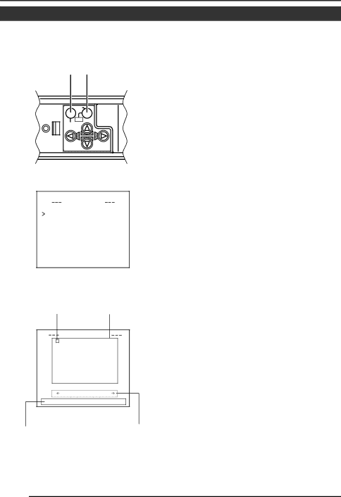
MENU button SET button

SET


CAMERA

AWC

SETUP

MENU


MODE S EL E C T

CAMERA T I T L E ED I T . .

RE V ERS E MODE

OF F

AL M . T I T L E S I Z E

D OUBLE

AL A RM COLOUR

WH I T E

AUX TERMINAL

(B&W IN)

D. ZOOM MAX

x2

MODE SELECT screen

Space

Character area

C AME R A

T I T L E

0 1 2 3 4 5 6 7 8 9 - : / . ,

AB C DE FG H I J K L MN O P

QR S T U VWX Y Z

a b c d e f g h i j k l mn o p

q r s t u v w x y z ’

ÄÖÜ ÂÊ Î Ô Û Ç Ñ

ä ë ï ö ü â ê î ô û á é í ó ú

à è ì ò ù ç ñ ß ¡ ¿

W I D E

T E L E

1.Select the item CAMERA TITLE on the MODE SELECT screen, and push the SET button.

Then, the CAMERA TITLE screen is brought up.

2.Select the first character from the

character area using buttons.

The selected character is displayed flashing on and off.

3.Push the SET button.

The first character gets fixed and the blinking title input area moves to the second character.

4.Repeat the above items 2 to 3.

It is possible to use up to 24 characters to input the title.

5.Push the MENU button.

The screen returns to MODE SELECT.

CAMERA TITLE screen

Title input area

Displayed when making


communication settings only

E-38

Image 38
Contents TK-C1430 Important Safeguards Page Safety Precautions Contents Reference page or item FeaturesMemo Operating Precautions Camera-mounting screw Hole 1/4 inch Controls, Connectors and IndicatorsLens mount Rotation-preventive holeButton VIDEO/DC Iris Selector SwitchCover 12 SET/AWC Set. Auto White Control Iris Iris Terminal17 RX.TERM-ON/OFF RX SignalTerminal ON/OFF Switch 15 INT/GL, LL Selector Switch for Synchronizing SystemDUPLEX, Simplex Selector Switch for Transmission System 13 , , , Up-and-down, left-and- right ButtonPower Power indicator lamp 22 Y/C OUT Y/C output connectorVideo OUT Video signal output connector This lamp lights when power is supplied to the cameraRM-P2580 System  System with up to 8 cameras Setting on the Menu screen   Connecting the control signal cable Setting the switches  When connectingProcedures Setting the switchesDC Iris Video Iris Mount the lens according to the procedures described belowMounting the lens VideoInstalling the ferrite core Connections on the back Control signal cables  Genlock connectionSpecified screw M3 ⋅ 6 mm Mounting the cameraFall Prevention Installation of camera Does not operate Lens adjustmentLevel adjustment Lens Focus Adjustment Mode Back focus adjustment Back focus adjustment With a fixed-focus lensAuto white balance control adjustment Error message displaySelected sub-menu screen is displayed Setting the menuMenu screen is displayed Change of the set value displays a change mark ∗Menu Setting Flow of menu screenC SE T T I NGS I S L E VE L Normal AV Erage P EAK Functions and set values Initial value Sync Adjust ScreenALC Settings Screen Memo Memo BLC PriorityMotion OFFAUX ColourMode AutoVideo Adjust Screen Mode Select Screen MAX Terminal MotionZoom Area Edit Alarm TimeMotion Detect Screen Communication Screen Maintenance ScreenFactory Settings Screen Sides having marks can be changed BLC Editting ScreenEDIT1 screen is brought up Manual Adjustment of White Balance Then, the Camera Title screen is brought up Camera Title SettingScreen returns to Mode Select Selected character is displayed flashing on and offSelect the item Area Edit on Setting the Motion Detect FunctionSetting screen is brought up Motion Detect screenOutput of Black-White/Color switching signal Set the B&W Item to AutoB&W/COLOR Mode screen appears Set the B&W item to AUXConfirm that the cursor is at the item White spot compensationOperation method CCD Spot screen will be dis- playedVideo OUT SpecificationsDimensions Unit mm OUTTK-C1430 Colour Video Camera