INTRODUCTION
Controls, Connectors and Indicators
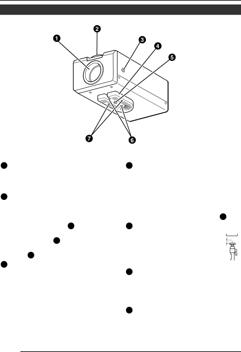
1Lens mount
To attach the lens.
This is applicable to both
2Back focus adjustment ring Adjusting the back focus during lens installation.
When readjustment is required, loosen the locking screw 3 by turning it counterclockwise and turn the back focus adjustment ring 2 .
After the adjustment, tighten the locking screw 3 again.
3[BF LOCK] Back focus locking screw This serves to fix the back
4
The bracket has been attached on the bottom of the camera before shipment. It can also be attached on the top according to the circumstance.
To
5Camera-mounting screw
hole (1/4 inch) |
|
|
|
|
|
| |
Use this hole when mounting |
|
|
|
|
|
| |
the camera onto a fixer, pan/ | MAX. | ||
tilt unit, and the like. (Use a | 7mm | ||
|
|
| |
screw shorter than 7 mm.) |
|
|
|
|
|
| |
6Rotation-preventive hole
Make use of this
7Camera mounting bracket fixing screws (⋅2: M2.6 ⋅ 6 mm)
Be sure to use a 6 mm long screw.