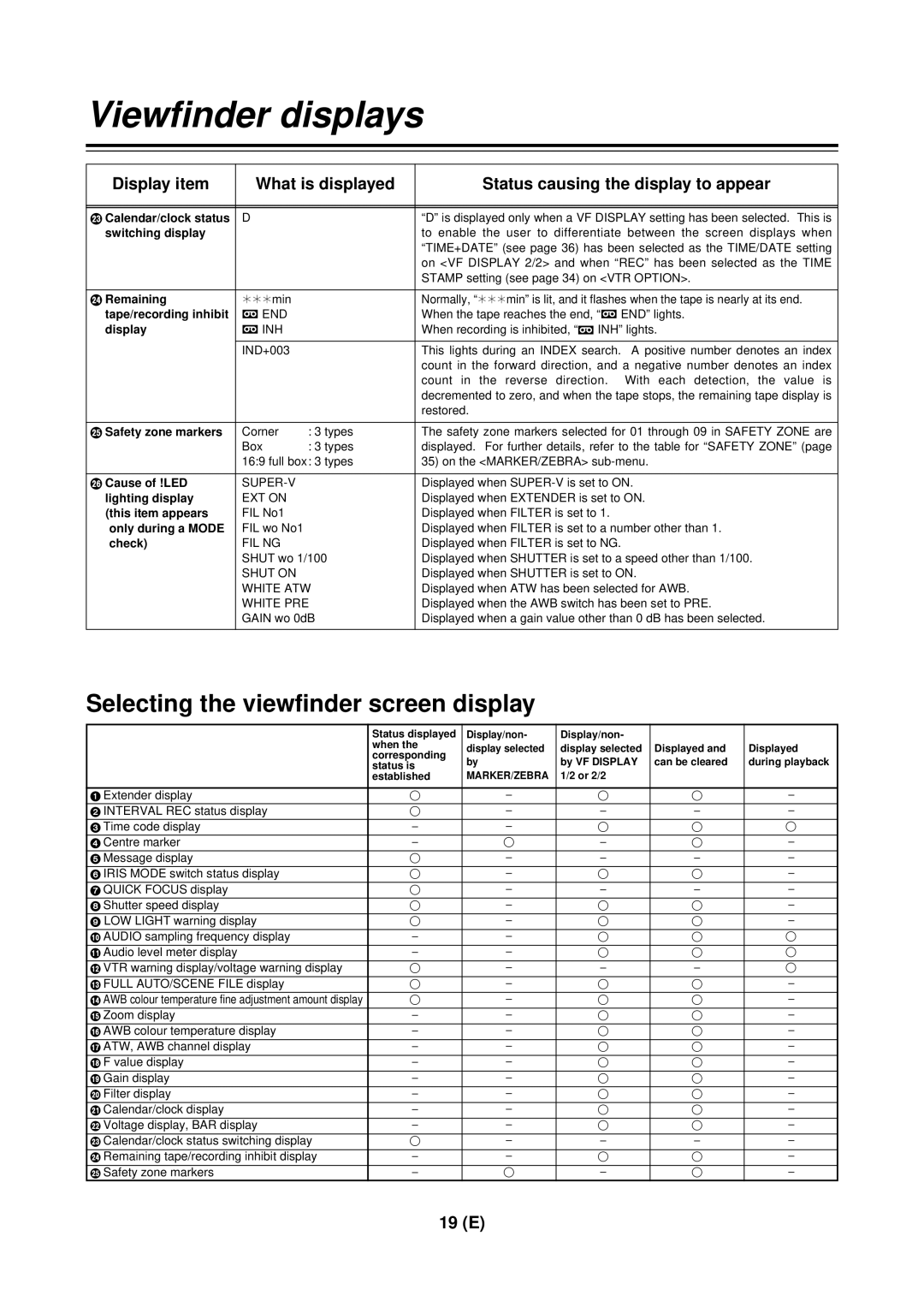
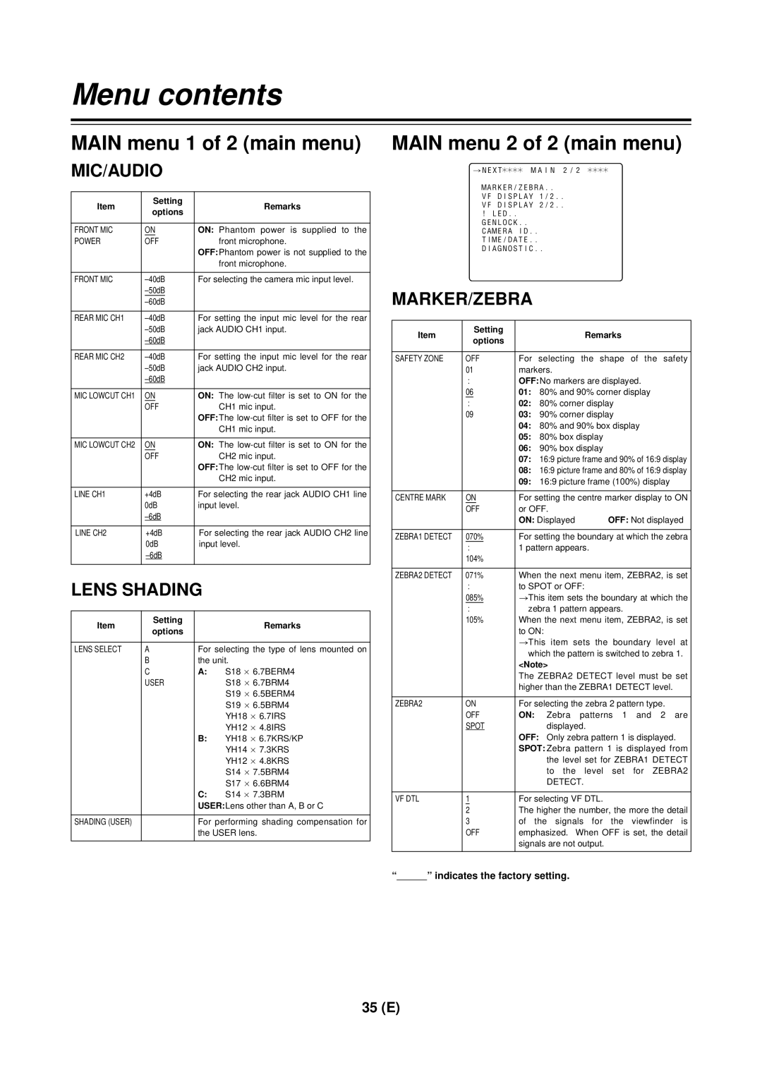
Viewfinder displays
Display item | What is displayed | Status causing the display to appear | |
|
|
|
|
|
|
|
|
G Calendar/clock status | D |
| “D” is displayed only when a VF DISPLAY setting has been selected. This is |
switching display |
|
| to enable the user to differentiate between the screen displays when |
|
|
| “TIME+DATE” (see page 36) has been selected as the TIME/DATE setting |
|
|
| on <VF DISPLAY 2/2> and when “REC” has been selected as the TIME |
|
|
| STAMP setting (see page 34) on <VTR OPTION>. |
|
|
|
|
H Remaining | ¢¢¢min |
| Normally, “¢¢¢min” is lit, and it flashes when the tape is nearly at its end. |
tape/recording inhibit | = END |
| When the tape reaches the end, “= END” lights. |
display | = INH |
| When recording is inhibited, “= INH” lights. |
| IND+003 |
| This lights during an INDEX search. A positive number denotes an index |
|
|
| count in the forward direction, and a negative number denotes an index |
|
|
| count in the reverse direction. With each detection, the value is |
|
|
| decremented to zero, and when the tape stops, the remaining tape display is |
|
|
| restored. |
|
|
|
|
I Safety zone markers | Corner | : 3 types | The safety zone markers selected for 01 through 09 in SAFETY ZONE are |
| Box | : 3 types | displayed. For further details, refer to the table for “SAFETY ZONE” (page |
| 16:9 full box: 3 types | 35) on the <MARKER/ZEBRA> | |
|
|
|
|
J Cause of !LED |
| Displayed when | |
lighting display | EXT ON |
| Displayed when EXTENDER is set to ON. |
(this item appears | FIL No1 |
| Displayed when FILTER is set to 1. |
only during a MODE | FIL wo No1 |
| Displayed when FILTER is set to a number other than 1. |
check) | FIL NG |
| Displayed when FILTER is set to NG. |
| SHUT wo 1/100 | Displayed when SHUTTER is set to a speed other than 1/100. | |
| SHUT ON |
| Displayed when SHUTTER is set to ON. |
| WHITE ATW | Displayed when ATW has been selected for AWB. | |
| WHITE PRE | Displayed when the AWB switch has been set to PRE. | |
| GAIN wo 0dB | Displayed when a gain value other than 0 dB has been selected. | |
|
|
|
|
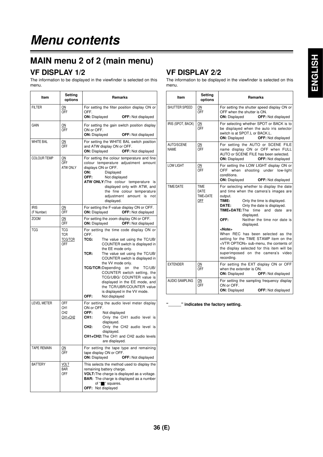
Selecting the viewfinder screen display
| Status displayed | Display/non- | Display/non- |
|
|
| when the | display selected | display selected | Displayed and | Displayed |
| corresponding | ||||
| by | by VF DISPLAY | can be cleared | during playback | |
| status is | ||||
| established | MARKER/ZEBRA | 1/2 or 2/2 |
|
|
|
|
|
|
|
|
1 Extender display | ≤ | – | ≤ | ≤ | – |
2 INTERVAL REC status display | ≤ | – | – | – | – |
3 Time code display | – | – | ≤ | ≤ | ≤ |
4 Centre marker | – | ≤ | – | ≤ | – |
5 Message display | ≤ | – | – | – | – |
6 IRIS MODE switch status display | ≤ | – | ≤ | ≤ | – |
7 QUICK FOCUS display | ≤ | – | – | – | – |
8 Shutter speed display | ≤ | – | ≤ | ≤ | – |
9 LOW LIGHT warning display | ≤ | – | ≤ | ≤ | – |
: AUDIO sampling frequency display | – | – | ≤ | ≤ | ≤ |
; Audio level meter display | – | – | ≤ | ≤ | ≤ |
< VTR warning display/voltage warning display | ≤ | – | – | – | ≤ |
= FULL AUTO/SCENE FILE display | ≤ | – | ≤ | ≤ | – |
> AWB colour temperature fine adjustment amount display | ≤ | – | ≤ | ≤ | – |
? Zoom display | – | – | ≤ | ≤ | – |
@ AWB colour temperature display | – | – | ≤ | ≤ | – |
A ATW, AWB channel display | – | – | ≤ | ≤ | – |
B F value display | – | – | ≤ | ≤ | – |
C Gain display | – | – | ≤ | ≤ | – |
D Filter display | – | – | ≤ | ≤ | – |
E Calendar/clock display | – | – | ≤ | ≤ | – |
F Voltage display, BAR display | – | – | ≤ | ≤ | – |
G Calendar/clock status switching display | ≤ | – | – | – | – |
H Remaining tape/recording inhibit display | – | – | ≤ | ≤ | – |
I Safety zone markers | – | ≤ | – | ≤ | – |
19 (E)