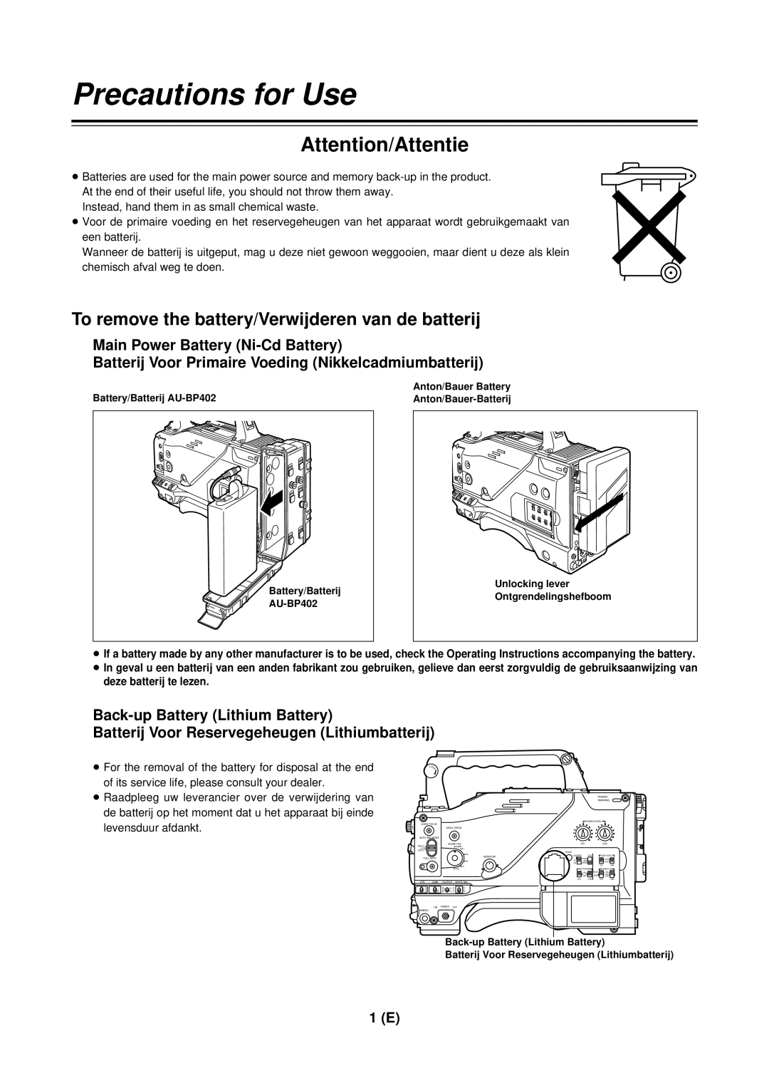
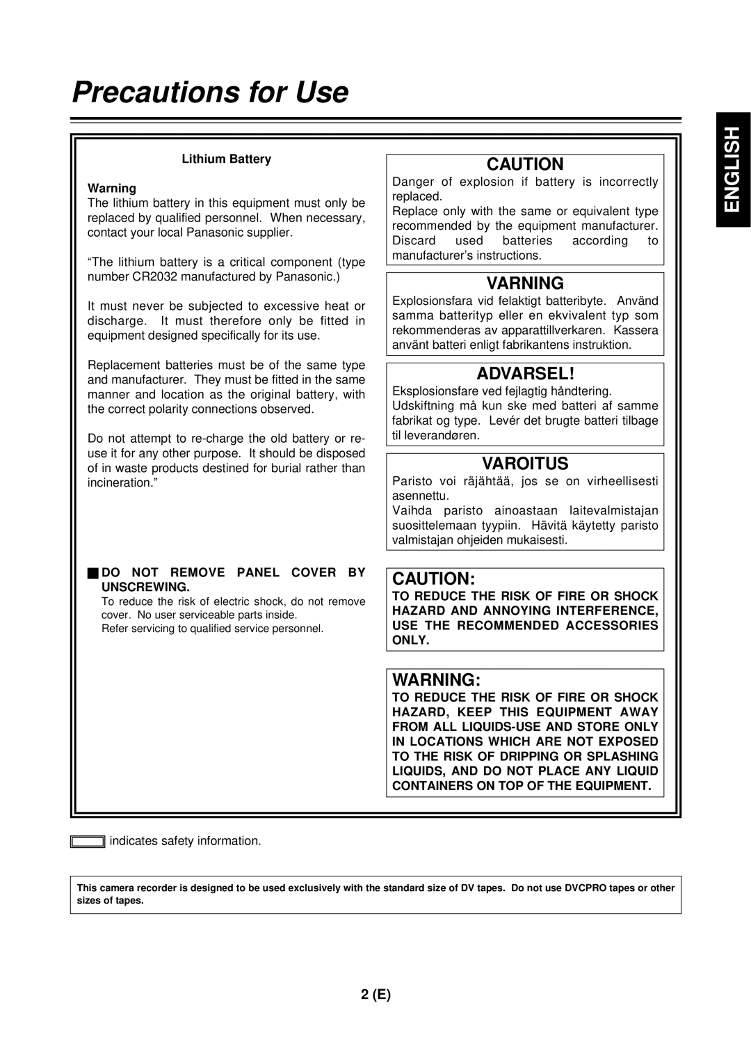
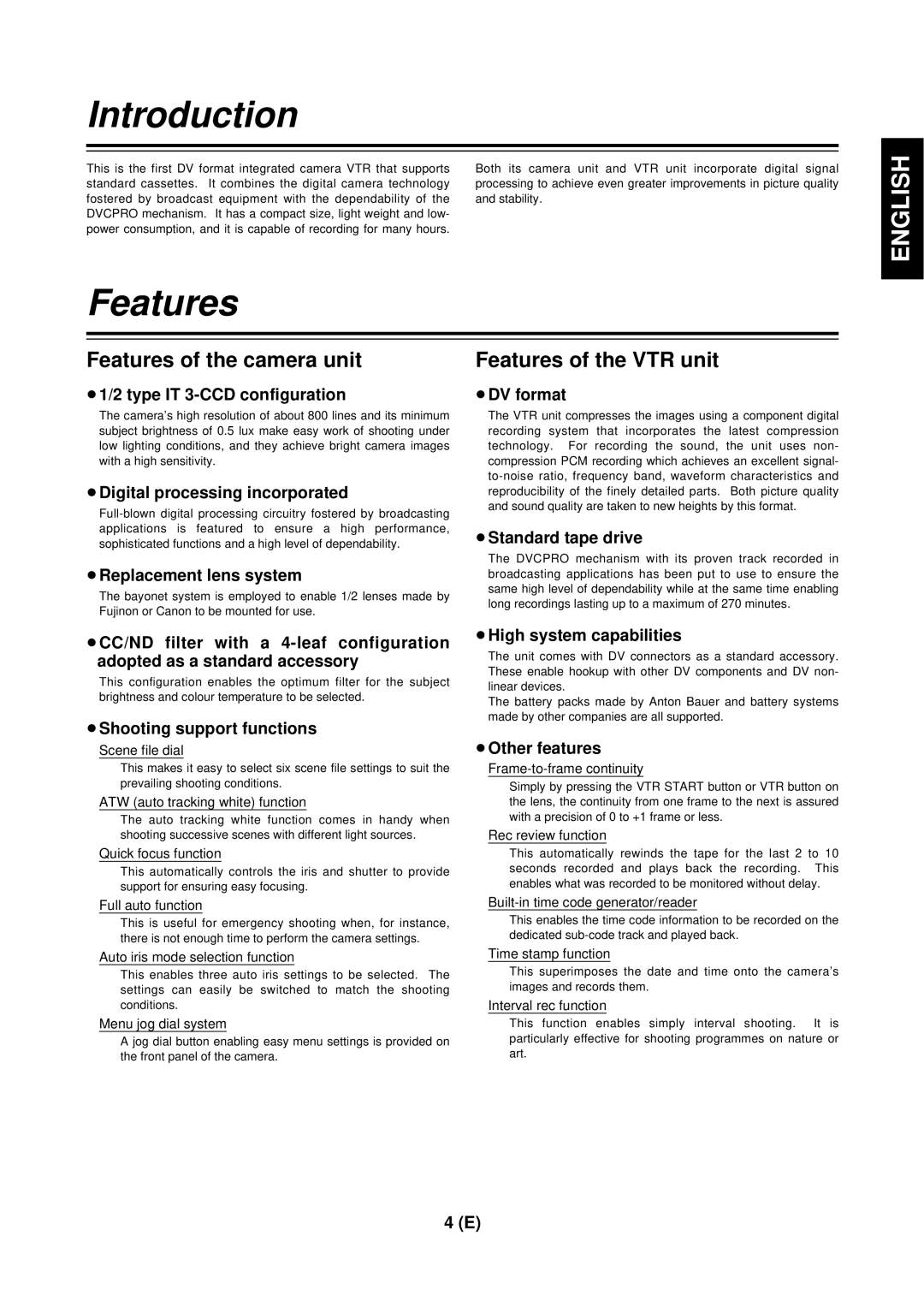
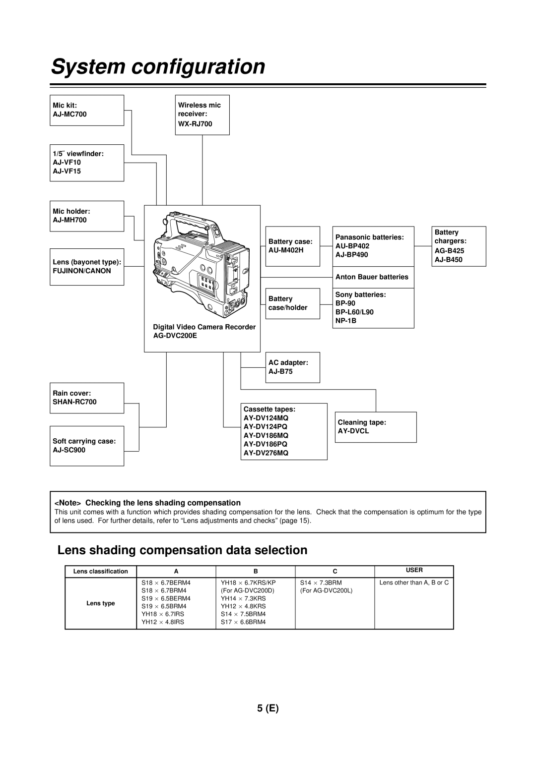
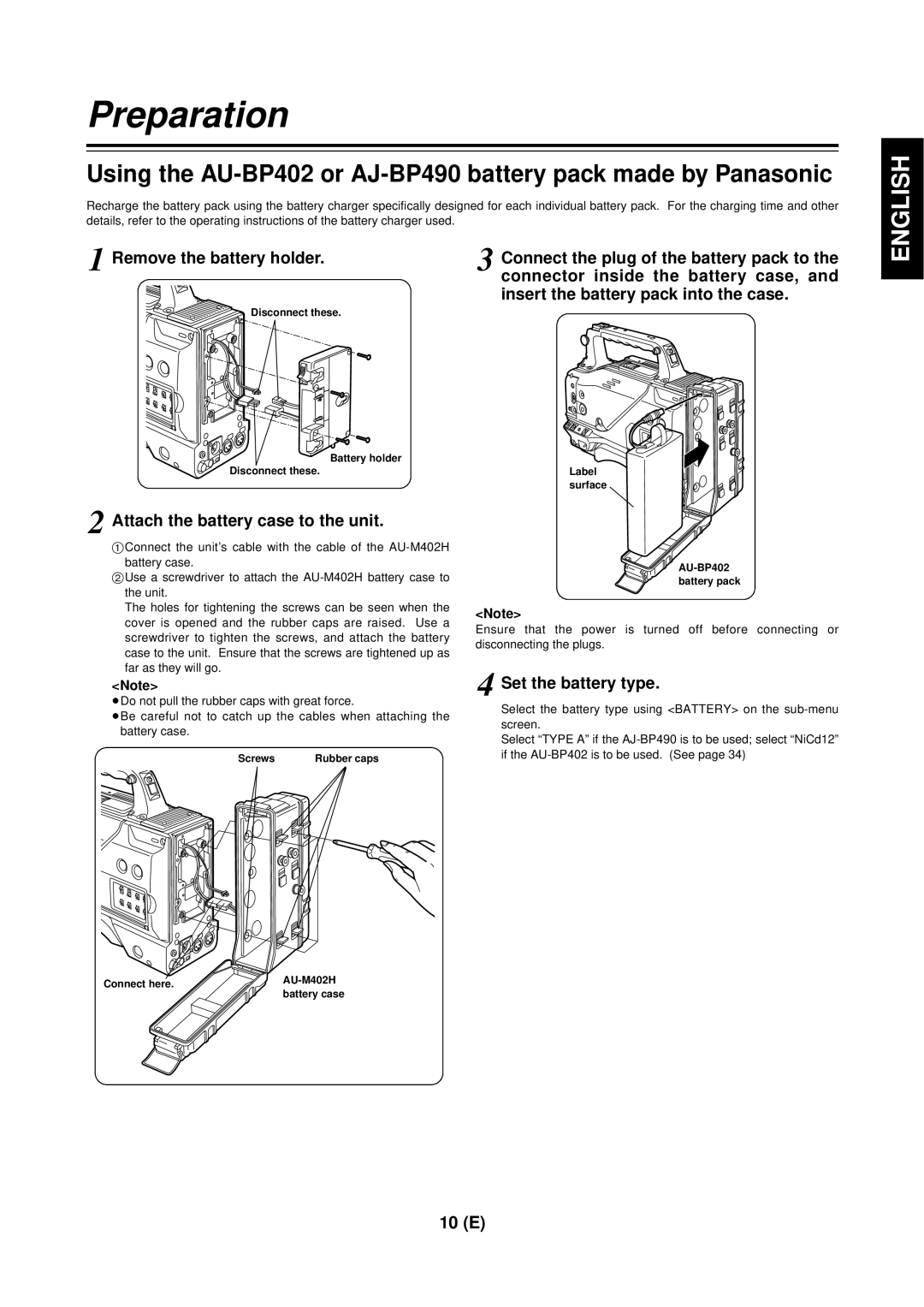
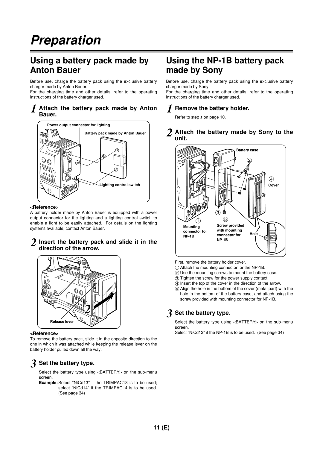
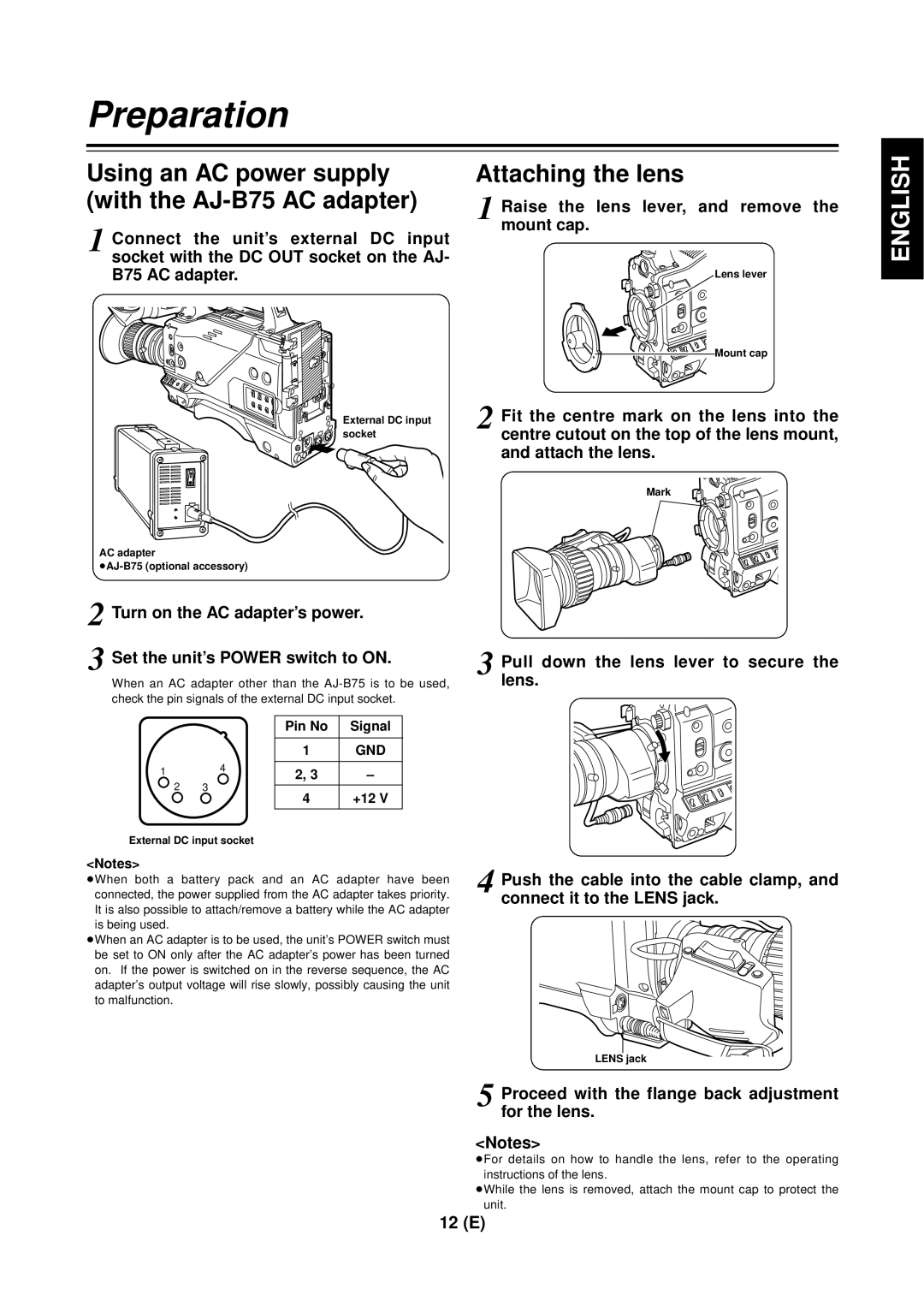
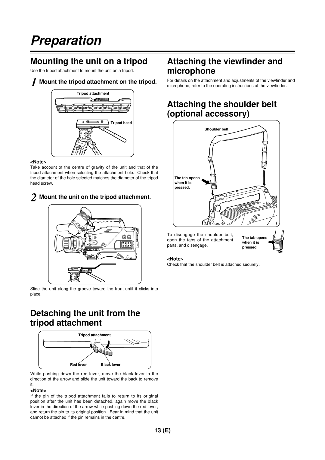
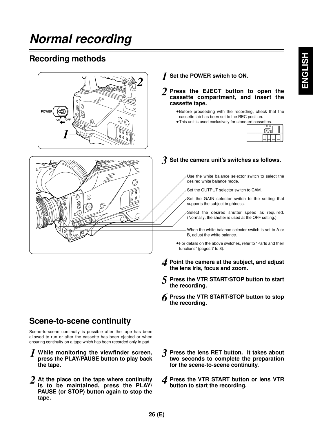
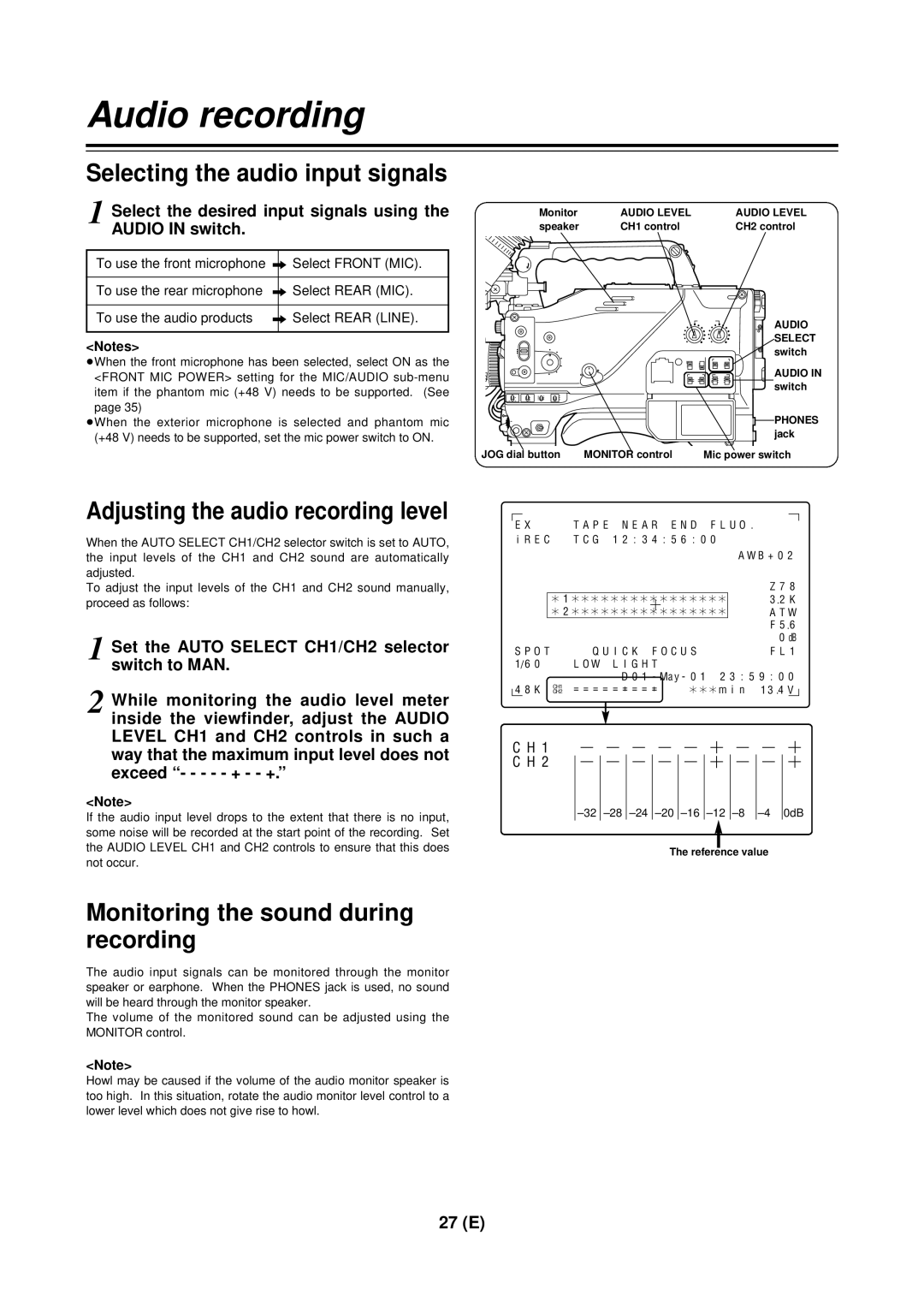
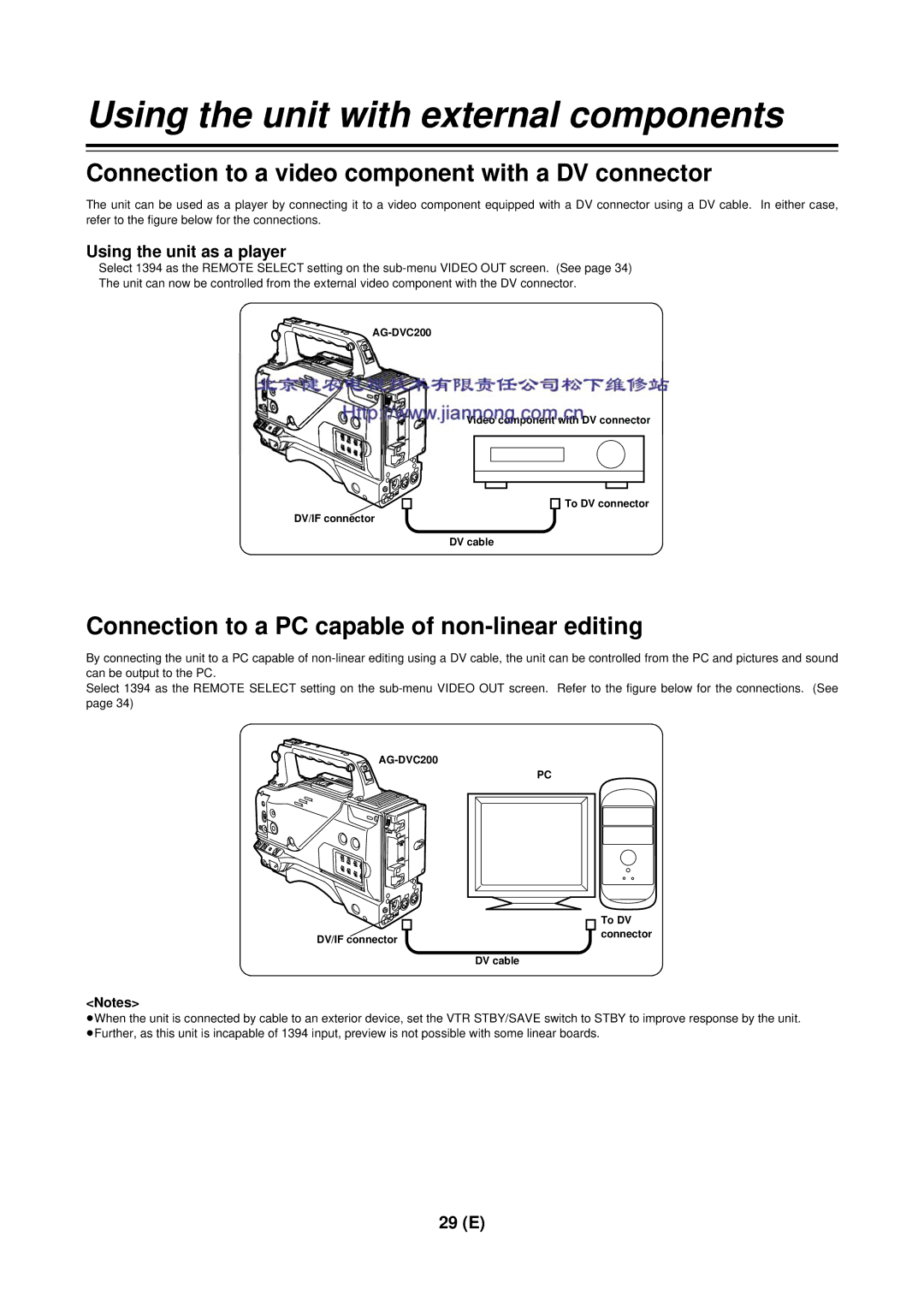
Panasonic AG-DVC 200E Tally lamp, External DC input socket, DC OUT DC power supply output socket

Page 10

Parts and their functions

1

2

3

4

7 6 5

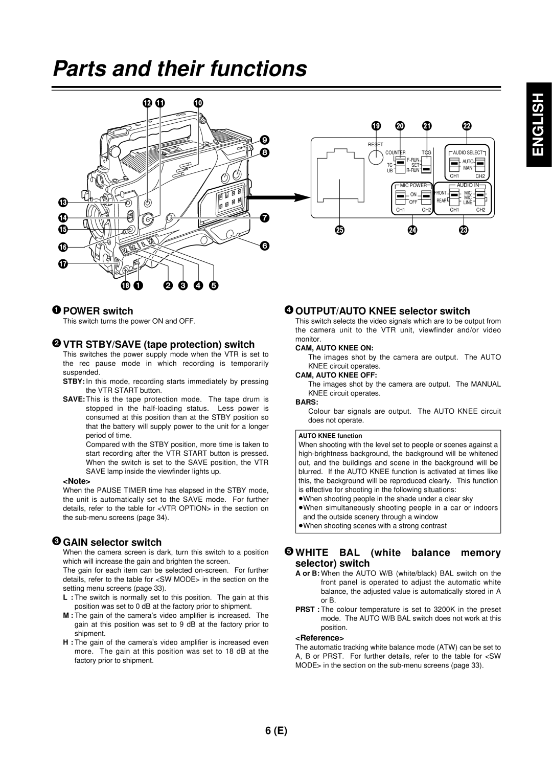
1TALLY lamp

This lights up when the unit is set to the recording mode. It flashes when it is being transferred to the recording mode.

2External DC input socket

This is the input socket of the external power supply (DC power supply). When an AC adapter is connected here, power is automatically supplied from the external source.

3AUDIO IN CH1, CH2 (audio input channel 1,

2) jacks (XLR, 3-pin)

An external microphone or line input signals are connected to these jacks.

4DV I/F connector (complying with IEEE

1394 standard)

A digital video component or computer equipped with a DV connector is connected to this connector using a DV cable (optional accessory). For further details, refer to “Using the unit with external components” (page 29).

5DC OUT (DC power supply) output socket

This normally serves as the DC 12 V output socket. A current of approximately 1 A can be taken out.

When the HDD adapter scheduled to be developed in the future is connected here, it will be possible to supply a 7 V voltage.

6VIDEO OUT jack (BNC)

This is the composite video jack for a monitor.

<Note>

When pictures are to be recorded with a backup VTR connected to the VIDEO OUT jack, bear in mind that the unit’s playback pictures will be recorded onto the backup VTR if any operation (such as REC CHECK) that performs VTR playback is executed. Use the exclusive camera output jack for backup recording.

8 8

6 5

/REWFF/

EJECT

STOP

PLAY/PAUSE

ª 1/;

; 9 :

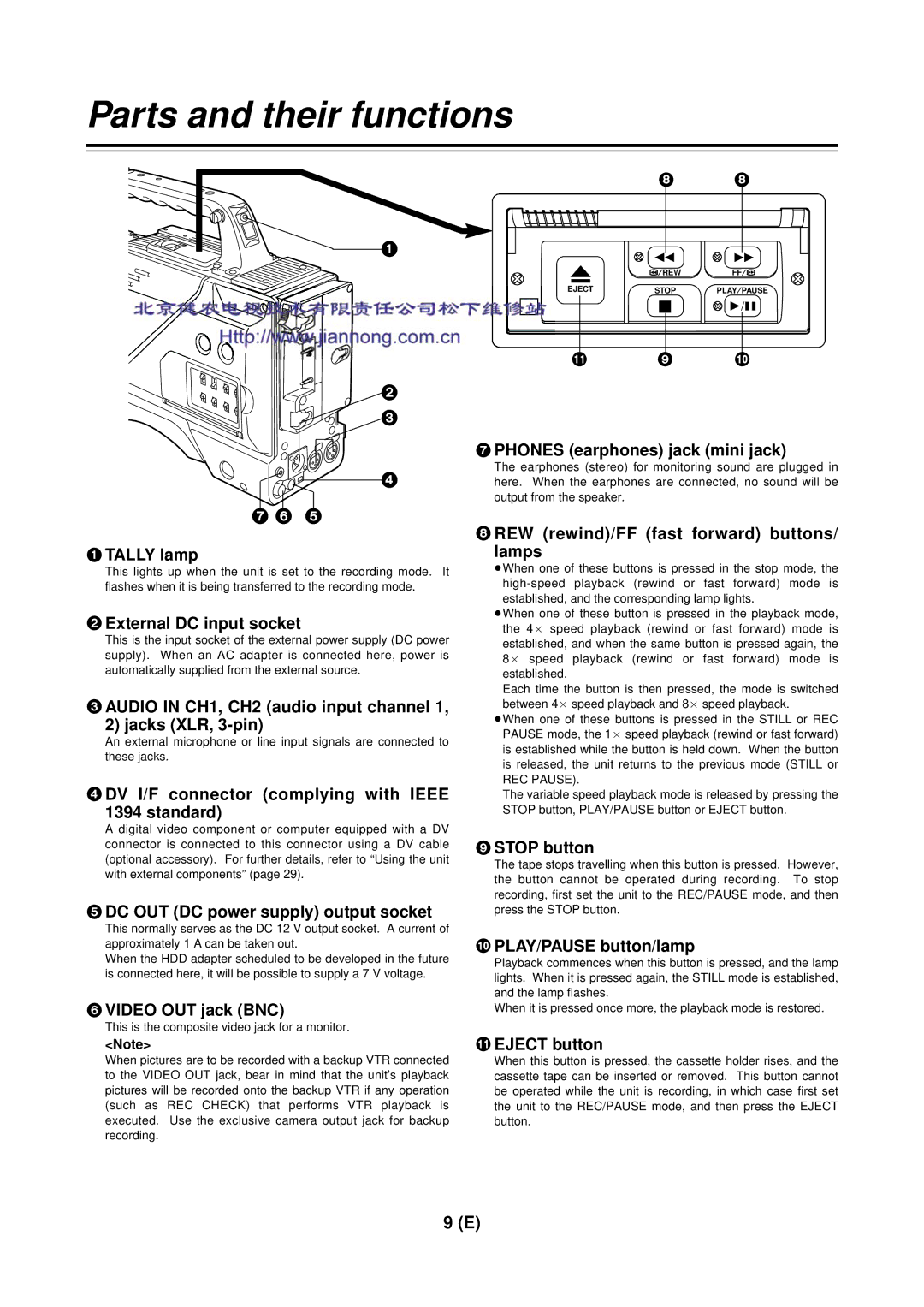
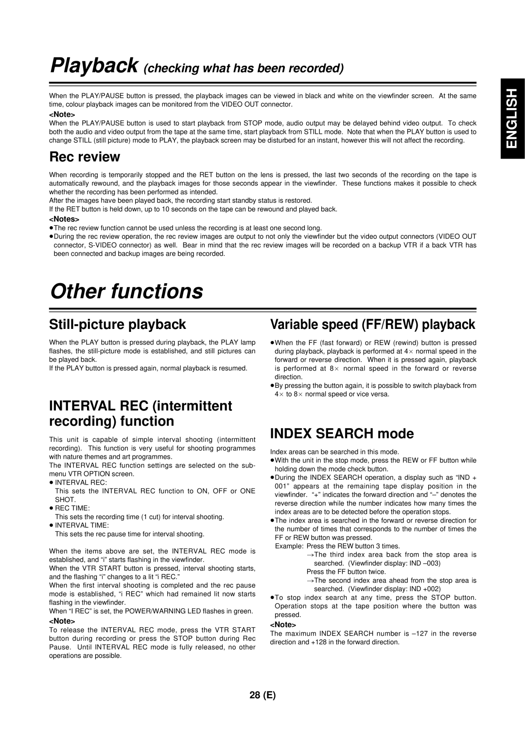
7PHONES (earphones) jack (mini jack)

The earphones (stereo) for monitoring sound are plugged in here. When the earphones are connected, no sound will be output from the speaker.

8REW (rewind)/FF (fast forward) buttons/

lamps

When one of these buttons is pressed in the stop mode, the high-speed playback (rewind or fast forward) mode is established, and the corresponding lamp lights.

When one of these button is pressed in the playback mode, the 4a speed playback (rewind or fast forward) mode is established, and when the same button is pressed again, the 8a speed playback (rewind or fast forward) mode is established.

Each time the button is then pressed, the mode is switched between 4a speed playback and 8a speed playback.

When one of these buttons is pressed in the STILL or REC PAUSE mode, the 1a speed playback (rewind or fast forward) is established while the button is held down. When the button is released, the unit returns to the previous mode (STILL or REC PAUSE).

The variable speed playback mode is released by pressing the STOP button, PLAY/PAUSE button or EJECT button.

9STOP button

The tape stops travelling when this button is pressed. However, the button cannot be operated during recording. To stop recording, first set the unit to the REC/PAUSE mode, and then press the STOP button.

:PLAY/PAUSE button/lamp

Playback commences when this button is pressed, and the lamp lights. When it is pressed again, the STILL mode is established, and the lamp flashes.

When it is pressed once more, the playback mode is restored.

;EJECT button

When this button is pressed, the cassette holder rises, and the cassette tape can be inserted or removed. This button cannot be operated while the unit is recording, in which case first set the unit to the REC/PAUSE mode, and then press the EJECT button.

9 (E)

Image 10 Contents
AG- E Digital Video Camera RecorderPrecautions for Use To remove the battery/Verwijderen van de batterijVaroitus Lithium BatteryVarning Do not Remove Panel Cover by UnscrewingContents Features Introduction Rain cover System configuration Cleaning tape Digital Video Camera RecorderParts and their functions Reset button Breaker switchMonitor volume control POWER/WARNING lampShutter switch Auto W/B white/black BAL switchGenlock in connector BNC = Viewfinder connectorTally lamp DV I/F connector complying with Ieee StandardDC OUT DC power supply output socket External DC input socketSet the battery type Remove the battery holderAttach the battery case to the unit PreparationAttachunit. the battery made by Sony to Using a battery pack made by Anton BauerUsing the NP-1B battery pack made by Sony AttachBauer. the battery pack made by AntonRaise the lens lever, and remove the mount cap Proceed with the flange back adjustment for the lensAttaching the lens Pulllens. down the lens lever to secureMicrophone Attaching the shoulder belt optional accessoryMounting the unit on a tripod Attaching the viewfinder Detaching the unit from the tripod attachmentSetting the date and time Setting the camera IDSpace ∏ Letters of the alphabet a through Z White shading adjustment Lens adjustments and checksFlange back adjustment White shading checkViewfinder lamp displays Viewfinder displaysViewfinder screen status displays Iris Mode switch Switch settingsError result message Extender displayTemperature display ATW, AWB channel Temperature fineAdjustment amount Shutter speedSelecting the viewfinder screen display Push the Auto W/B BAL switch to ABB and release it White balance and black balance adjustmentSet the switches to the positions shown in the figure 50 HzPushSEL. the Shutter switch from on to Electronic shutter settingsSetting the synchro scanning mode Shutter modesSetting the time code Time data settingsSetting the user’s bit Set the TCG switchScene file function Scene file setting methodScene files Editing scene filenamesRotate the JOG dial button to move to the Write item How to use file selectReturning a scene filename to its default Press the Menu button to exit the menu operationList of scene file settings List of file settingsRecording methods Set the camera unit’s switches as followsNormal recording Scene-to-scene continuitySelect the desired input signals using the Audio in switch Selecting the audio input signalsAdjusting the audio recording level Audio recordingOther functions Using the unit as a player Using the unit with external componentsConnection to a video component with a DV connector Connection to a PC capable of non-linear editingUpon completion of the settings, press the Menu button Menu display enable/disableDisplaying sub-menus and deciding on settings Menu operationsMain 1/2 Setting menu configurationMain 2/2 Menu contents Process SW ModeMain menu 1 of 2 main menu Additional ProcessVTR Function BatteryVideo OUT VTR OptionLens Shading Main menu 2 of 2 main menuMIC/AUDIO MARKER/ZEBRAVF Display 1/2 VF Display 2/2Genlock DiagnosticLED Camera IDServo SlackREC Warning HumidSet the power to OFF Battery ENDBattery Near END Emergency ejectMaintenance Error codesAudio system SpecificationsVideo system Tape transport systemOutput Optional accessory AJ-VF10Input OtherVQT9278-1 F0401T1051 @