Installation ~ LCD Programming | 25 |
Echo canceller |
|
Activate or deactivate the echo cancellation feature for each gated input. Factory default is on.
NLP adjust
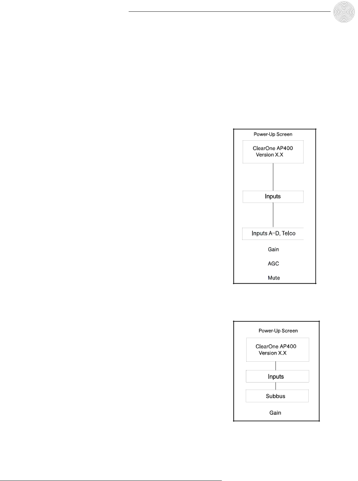
Inputs A-D, Telco
The parameter submenus below this level control how inputs A, B, C, and D and Telco In deal with input audio. Three input parameters can be applied to the inputs: gain adjust, AGC and mute (see Figure 2.16).
Gain
This adjusts each input’s gain (ranging between
AGC
Each input can use automatic gain control (AGC). This feature keeps softer and louder input audio at a consistent level. This feature is disabled when shipped from the factory.
Mute
This parameter mutes a particular input channel.
Figure 2.16. Inputs A–D submenu
Subbus
The subbus parameter allows control of gain (attenuation) of mix audio from the microphones into the speaker audio. The attenuation can be adjusted in dB.
Gain
The subbus gain can be adjusted over a range of 0 to