Grizzly G0648 owner manual

Page 33

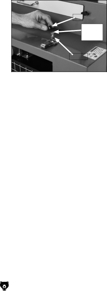
18.Grasp the spring and insert the top of it on the end of the retaining bolt that protrudes into the cabinet.

Note: With the top of the spring being held in place by the end of this bolt, compressing and positioning the bottom of the spring into its seat is much easier.

19.When the spring is installed, thread the retaining bolt by hand all the way down until it seats into the hole in the top of the vibrating filter and stops.

20.At this point, un-thread the retaining bolt approximately 11/2" turns and lock the jam nut down against the cabinet so the bolt holds this position (Figure 39).

Note: The clearance between the end of the bolt and its seat gives room for the filter to vibrate but not fall out of position.

G0648 Welding Fume Extractor

Cap

Spring

Retaining

Bolt

Jam Nut

Figure 39. Vibrating filter retainer.

21.Place the cap onto the spring retaining bolt.

22.Clean or replace the HEPA filter as discussed on Page 32.

-31-

Image 33
Contents Model G0648 Welding Fume Extractor Ss ,EAD from Leadbased PAINTS Table of Contents Introduction Foreword Functional OverviewContact Info Identification Vibrating Filter & Hepa Filter HousingMachine Data Sheet Other Specifications  !,7!93 53%3 %!2.2 02/4%#4/ %. /0%2!4.! -!#.%29  !,7!93 53% !.3 !002/6%$$ 3!&%49 ,!33%33 7%. /0%2!4 53%3 2%#/--%.$%$- !##%33/2%3  53%3!!2/5.$%$ %84%.3/..#/2$ 2!4%$4&/2/4%-!#.%!-0%2!%2 -!.9 -!#.%3 #!. %*%#4 7/2+0%#%3 4/7!2$ /0%2!4/2  !,7!93 ,/#+ -/,% !3%3 & 53%$ % %&/2% /0%2!4. -!#.%29#Additional Safety Instructions for Welding Fume Extractors Meeting Welding Fume Extraction Codes Standards Circuit Requirements 220V 3-Phase OperationSetup Safety SetupItems Needed for Setup UnpackingInventory Crate 1 Figure QtyBox 2 Figure Qty Hardware Recognition Chart Floor Load Site ConsiderationsTo install the ducting arm Ducting Arm InstallationTest Run To test run the machineCompletely open both blast gates on the ducting arm Figure Operation Safety General Operation OperationsTo use the machine Page Setting Time Left Button Controls Setting Time Right Button ControlsControl Panel Operation To change the rolling-filter timing Changing Rolling Filter TimingModel G0648 Rolling Filter Consumption Chart T20474-First Layer Stainless Screen AccessoriesT20475-Second Layer Paper Filter Roll T20529-Third Layer FilterH7217-Rigid Flex Hose H5297 6 Welding Fume Collection KitSteel 6 Elbows G7366 6 G7368 6 G7367 6 G7369 6 90G7370 6H3157-Deluxe Welding Gloves Model T20505 welding respiratorCleaning MaintenanceSchedule LubricationTo perform this procedure Slag-Screen CleaningLong-Term Storage Tools Needed QtyRemoving recovery axle Rolling-Filter ReplacementPage Vibrating Filter Manual Cleaning Page Page To clean the Hepa filter Hepa Filter Manual CleaningPage Service TroubleshootingSymptom Possible Cause Possible Solution Operation Electrical Safety Instructions Wiring220 VAC Wiring OverviewMain ELE BOX Main Electrical Box WiringMain Electrical Box Components Input relay, fuse bus, phase Controller Transformer PigtailControl Panel WiringMAIN ELE Cntrl Digital Control Panel Electrical ComponentsMOT Cabinet WiringVibrating Cabinet Electrical ComponentsMain Parts Breakdown PartsDescription Parts ListMotor 2HP 220V 3PH Blast Gates and Ducting Arm Breakdown Parts List Main Electrical Box Label Placement G0648 Welding Fume Extractor 22!.49 #!2$ 99.$5342!, .# 0//88 %,,.!- 7!  Warranty and Returns #ALL 4ODAYD&ORO! &2%%