Graco 3A2495C important safety instructions Alternator Removal and Replacement

Page 46

Repair

Alternator Removal and Replacement

NOTE: Replace alternator bearings after 2000 hours of operation. Order Part No. 24N706 Bearing Kit. Parts included in the kit are marked with a symbol (♦).

1.See Prepare the Gun for Service, page 39.

2.Remove the power supply/alternator assembly and disconnect the alternator. See Power Supply Removal and Replacement, page 45.

3.Measure resistance between the two outer terminals of the 3-wire connector (PC); it should be 2.0–6.0 ohms. If outside this range, replace the alternator coil (15a).

4.Using a flat blade screwdriver, pry the clip (15h) off the housing (15d). Remove the cap (15f), using a thin blade or screwdriver.

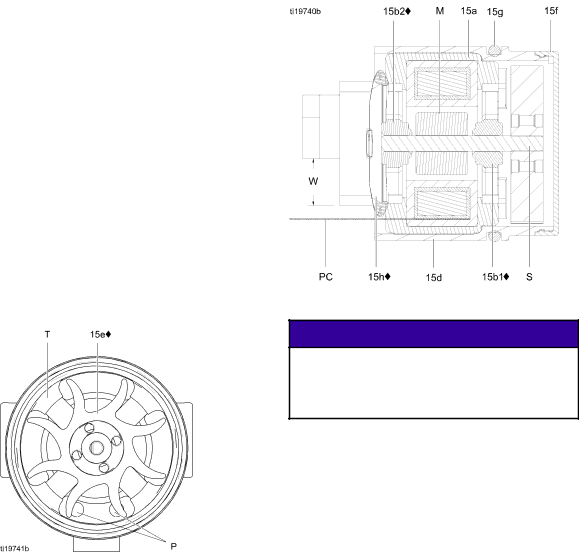
5.If necessary, rotate the fan (15e) so its blades clear the four bearing tabs (T) of the housing (15d).

Figure 34 Fan Orientation

6.Push the fan and coil assembly (15a) out the front of the housing (15d).

Figure 35 Alternator Cross-Section

NOTICE

Do not scratch or damage the magnet (M) or shaft (S). Do not pinch or damage the 3–wire connector (PC) when disassembling and reassembling the bearings.

7.Hold the coil assembly (15a) on a workbench with the fan end facing up. Using a wide blade screwdriver, pry the fan (15e) off the shaft (S).

8.Remove the top bearing (15b2).

9.Remove the bottom bearing (15b1).

10.Install the new bottom bearing (15b1♦) on the long end of the shaft (S). The flatter side of the bearing must face away from the magnet (M).

Install in the coil (15a) so the bearing blades are flush with the surface of the coil.

11.Press the new top bearing (15b2♦) onto the short end of the shaft so the bearing blades are flush with the surface of the coil (15a). The flatter side of the bearing must face away from the coil.

46

3A2495C

Image 46
Contents Important Safety Instructions InstructionsContents Smart Display Standard Display II 2 GFIRE, EXPLOSION, and Electric Shock Hazard Skin Injection Hazard Equipment Misuse Hazard Gun Overview How the Electrostatic AA Spray Gun WorksDescription Purpose Chart, page 62, for availSetup Checklist, See Spray Tip SelectionOperating Mode Bar Graph Smart GunsError Display Key for Figs Description Purpose Description Purpose Diagnostic Mode Alternator Speed Hertz Screen Installation Ventilate the Spray BoothFluid Supply Line Air Supply LineHose Typical Installation Key Description NON-HAZARDOUS AreaGun Setup Gun Setup ChecklistGun Setup LED Indicator Colors Description Pressure DropGrounding Key to Figs Ground the Operator Ground the Gun Check Gun Electrical Grounding Check Fluid Viscosity Flush Before Using EquipmentCheck Fluid Resistivity Fluid Resistivity Levels Megohms-cmStartup Pressure Relief ProcedureOperation ShutdownMaintenance FlushingClean the Gun Daily Maintenance Daily System Care Check Gun Electrical Grounding,Electrical Tests Test Gun ResistanceTest Power Supply Resistance Alternator Removal and Replacement,Test Gun Barrel Resistance Problem Cause Solution TroubleshootingSpray Pattern Troubleshooting Clean the Gun Daily,Gun Operation Troubleshooting Replacement, page 45 Replacement,Power Supply Removal Test Gun Resistance,See Clean the Gun Daily, Replacement, page 52Prepare the Gun for Service RepairAir Cap, Spray Tip, and Fluid Seat Housing Replacement See Prepare the Gun for Service,Electrode Replacement See Test Gun Resistance,Fluid Filter Replacement Fluid Tube Removal and ReplacementGun Barrel Installation Gun Barrel RemovalFluid Needle Replacement Remove Cap and SpringsPower Supply Removal and Replacement See Prepare the Gun for Service, See Gun Barrel Removal,Alternator Removal and Replacement Alternator Fan Air Adjustment Valve Repair Fan Air Adjustment ValveAtomizing Air Adjustment Valve Repair ES On-Off Valve Repair See Gun Barrel Installation, Air Valve RepairSmart Module Replacement Smart ModuleAir Swivel and Exhaust Valve Replacement Air Inlet Fitting and Air Exhaust ValveStandard Air-Assisted Spray Gun Assembly PartsDescription Qty Smart Air-Assisted Spray Gun Assembly See Smart Module Assembly Alternator Assembly Part No N664 Alternator AssemblyES On-Off Valve Assembly Part No N632 ES On-Off Valve AssemblyFan Air Valve Assembly Part No N634 Fan Air Valve AssemblyAir Cap Assembly Smart Module Assembly Spray Tip Selection Chart AEM Fine Finish Spray TipsOz/min l/min AEF Fine Finish Pre-Orifice Spray TipsOrifice Fluid Output 41 bar MPa Bar Spray TipSystem Accessories Repair Kits, Related Manuals, and AccessoriesGun Accessories Test EquipmentOperator Accessories HosesDimensions Gun Model In. mm Weight, oz gTechnical Data Graco Pro Xp Warranty Graco Information