Chateau™ Decorative Gas Appliance
Accessories
Remote Controls
Optional remote control units are available to control different functions of the appliance.
Model | Function(s) Controlled |
RC1 | On/Off |
RC2 | On/Off and Temperature |
IMTFK | |
| (For use in Canada ONLY) |
|
|
| Full Surround Mantel |
|
|
The Chateau Full Surround has been designed for installation with the DVT38S2 Chateau fireplace. Hinged face panels on the surround allow access to the fireplace control box and gas valve. Accurate framing of the fireplace is critical to proper installation.
Refer to the instructions supplied with the Surround for complete details.
CAUTION: If you are framing with the plan to use the surround mantel mentioned above, it is extremely critical to meet the dimensions provided, especially if the mantel is not available at the time of framing.
NOTE: In the event the mantel is not available at the time of framing the unit/valve box, you must make the spacer on the left side of the valve box in order to access the valve box door through the opening in the mantel.
Full Surround Mantel Models:
CHFN049S
CHFWC49S
CHFPR49S
NOTE: The vertical dimension is shown from the floor where the fireplace sits. If a marble hearth extension, or other type of material is used, the vertical framing will increase by the thickness of the material used to ac- commodate the height difference when the mantel sits on the hearth extension.
3 x 12 Control box Spacer ‘G’
48���" | 11/16" |
| |
(1222 mm) |
| ||
| (17 mm) | Framing | |
| 24���" | Cross | |
| Piece | ||
(613 mm) | |||
| |||
CL of Glass |
| ||
(Not Unit) |
| ||
|
| 45���" | |
Critical | (1149 mm) | ||
| |||
Dimension |
| ||
![]() 3“ (76 mm)
3“ (76 mm)
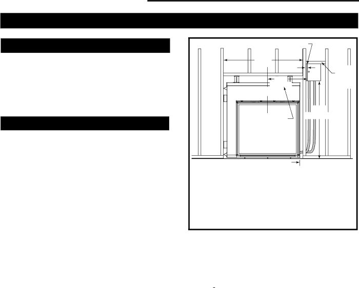
Position the DVT38S2 fireplace in the rough opening. Measure up from the floor 45¹⁄₄” and attach the control box spacer (G) to the inside of the wall stud. Attach a fram- ing cross piece between the studs, above the control box spacer. Fit the control box tight against the spacer (G) and the frame piece above. Fasten the control box to the frame piece with 1¹⁄₄” screws through the holes in the top of the
control box. | FP1479 |
Fig. 63 Chateau Full Surround Mantel framing.
CAUTION: If you are framing with the plan to use the CHFN0495, CHWC495, CHFPR495 surround mantel, it is extremely critical to meet the dimensions provided, especially if the mantel is not available at the time of framing. A framing stud is allowed to be placed on the inside of the 6” (152 mm) standoff on the side of the unit where the conduit is located to meet the 24¹⁄₈” ( 613 mm) critical dimension from the center of the unit.
The unit is certified with a 3” (76 mm) standoff (to combustible) on the side of the unit where the conduit is located, therefore; it is permissible to locate stud on the inside of the standoff at 3” (76 mm) from the body of the unit. (Fig. 63)
NOTE: The 6” (152 mm) standoff is sent out with the unit for the purpose of making the glass symmetrical with respect to the overall width of the unit.
38 | 20009543 |