Enviro C-10381, C-11290 owner manual To Replace, Handles for Removing Door

Page 10

Maintenance And Service

Replacing the Glass:

The glass in the fireplace is a high temperature ceramic. If the glass is damaged in any way, a factory replacement is required (see Parts List - Components). Wear gloves when handling damaged glass door assembly to prevent personal injury. When the glass door assembly is being transported, it must be wrapped in newsprint and tape and/or a strong plastic bag. Do not operate with the glass front removed, cracked or broken. Removal and replacement of the glass from the door must be done by a licensed or qualified service person. The glass must be purchased from an ENVIRO dealer. No substitute materials are allowed.

To Replace:

Open door, and remove the glass carefully.

Install the new piece of glass with the large bulb in the gasket tape against the unit. Place the joint in the tape in a bottom corner. Close door.

Glass Door Removal:

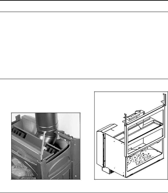
Turn unit off and wait until the appliance has cooled down. Remove the cast iron top from the unit by lifting straight up. Lift the two door handles located on either side of the door and lift the glass door assembly straight up and out (see Figure 6 and 7).

Carefully open the two doors and remove if necessary.

Ensure the door is properly fastened after cleaning before attempting to re-light the appliance.

Figure 6: Handles for Removing Door.

Figure 7: Removing of Door.

Burner Removal:

1.Remove the glass as shown in the Maintenance and Service - Glass Door Removal.

2.Carefully remove the log set and ember material.

3.Remove the two (2) screws (located on the outside edges of the burner) that hold the burner to the

chassis inside the fire box, see Figure 8. Remove the burner tray from the firebox.

10

Image 10
Contents Installer ConsumerSafety Precautions GeneralTable of Contents TOP Vent DV Codes And ApprovalsRear Vent DV Specifications Westport Exterior DimensionsOperatingInstructions MAYOperating Instructions Pilot FlameComponent Sound & Reason Maintenance And Service Electronic Ignition Module LocationTo Replace Handles for Removing DoorKit Parts List Conversion Kit InstallationRemove the black protection cap from Initial Installation Qualified Installers onlyRound Support Vent Termination Restrictions Installation Instructions KIT ComponentsInstallation of Fireplace Horizontal Vent Kit Manufacturer Trade Name Nominal Sizes4DSC Shows the vent restrictor position required, relative to 51mm at top, 1½ 38mm at sides, 1½ 38mm at Bottom Twist-Lock ConnectionTermination Pipe and elbows may be utilized in the attic, as Over 18/12 to 20/12 Over 20/12 to 21/12 Follow installation steps 1 & 2 under Initial Do not interfere with the structural integrity of the walls 33a-2002 Test Methods and the Resulting ITS Firebox Top Corner Installation Installation for Top Vented Horizontal TerminationCanadian Installations InstallationWiring Diagram A. InstallationsVenting of a Fireplace Fitted with the Drafthood Adaptor Spillage TestSpill Switch Replacement Automatic Safety Shut DownOptional Finishing GAS Line Connection To Test Valve PressuresWire Size Max. Length Wiring Diagram For Fan ControlSecondary Installation Optional Blower Fan InstallationComplete Log Placement Log Placement with Rock Wool Brick panel bracket, slots shown Trouble Shooting Problem Possible Cause SolutionParts List Cast Reference Part Description Part NumberEGWP-505PG EGWP-501PG Parts Diagram Cast Parts List Components Parts List Components Parts Diagram Components Warranty To the DealerWarranty Installation Data Sheet