Bissell HS-20 instruction manual Asa

Page 17

Installation

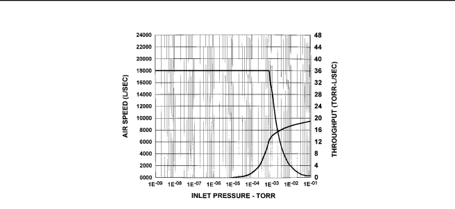
Figure 1-1. Speed and Throughput Curves – HS-20 Diffusion Pump

1-3

PHYSICAL SPECIFICATIONS (See Figure 1-2)


Flange dimensions (inches):


ASA


ISO 630k

ISO 160k


Inlet


Foreline

Inlet

Foreline

OD


27.50


9.0

27.17

7.09


ID


21.25


5.06

21.25

5.06


Thickness


1.12


0.75

0.78

0.47


Bolt Circle


25.0


7.5


No. of Holes


20.0


8.0

Requires NW-630

Requires NW-160


Size of Holes


1.25


0.75


Centering Ring (not

Centering Ring (not


Orientation


Straddle center line


included with pump)

included with pump)


Gasket Groove ID


21.625


5.31


wide


0.48


0.375


deep


0.25


0.09


Height

48 inches; allow additional


8 inches (min) for heater removal

Jet Assembly 5-stage, Self-aligning, fractionat- ing design with four diffusion stages and one ejector stage

Foreline

Stacked disk and ring

Baffle


Cold Cap

Water-cooled

Water

14

FPT body and foreline

Connections

38

quick cool coils

Thermal

Upper set at 185°F (29°C)

Switches

Lower set at 390°F (93°C)

Materials

Body: Mild steel


Flanges: Mild steel


Jet Assembly: Aluminum


Foreline Baffle: Stainless Steel


Cooling Coils: Copper


Quick Cool Coils: Stainless Steel


Cold Cap: Copper (Nickel-plated)

Weight

500 pounds

Shipping

580 pounds

Weight


1-2

Image 17
Contents HS-20 Diffusion Pump Sales and Service Offices Telephone Numbers Warranty Replacement and Adjustment WarrantyPage Page Iii Prohibited Action Explosion-Causing Condition Prohibited Action Result Page Vii Page Page Section Safety Considerations Section I Installation Table of ContentsList of Tables List of IllustrationsModel Technical Specifications Installation GeneralOperating Specifications See Figure ASA Outline Drawing HS-20 Diffusion Pump, with ASA Flanges Unpacking Cleaning a NEW PumpInstallation Utility and System Connections Safety Considerations and InterlocksVacuum Connections Cooling Water Connections See FigureCooling Water Connections Initial Vacuum Test Thermal Switches240/400/430/440/480 V Wiring Diagram HS-20 Diffusion Pump 415 V Wiring Diagram HS-20 Diffusion Pump Adding Pump Fluid Sight Glass Assembly Operation START-UP ProcedureOperation Shutdown ProcedurePeriodic Inspection Maintenance GeneralCleaning MaintenanceDo not overtighten the screw Disassembling and Reassembling the Cold CAP Refer to FigureExternal Fittings Cold Cap Assembly Disassembling the Lower Jet Assembly JET AssemblyDisassembling the Jet Assembly Refer to Figure Inch Jet Assembly Heater Replacement Maintenance Reassembling the Lower Jet AssemblyReassembling the Jet Assembly Jet Coupling Tighten clamping nuts to 250 in.-lbs Maintenance Replaceable Parts Maintenance Poor Pump or System Performance Troubleshooting LeakageOutgassing Troubleshooting