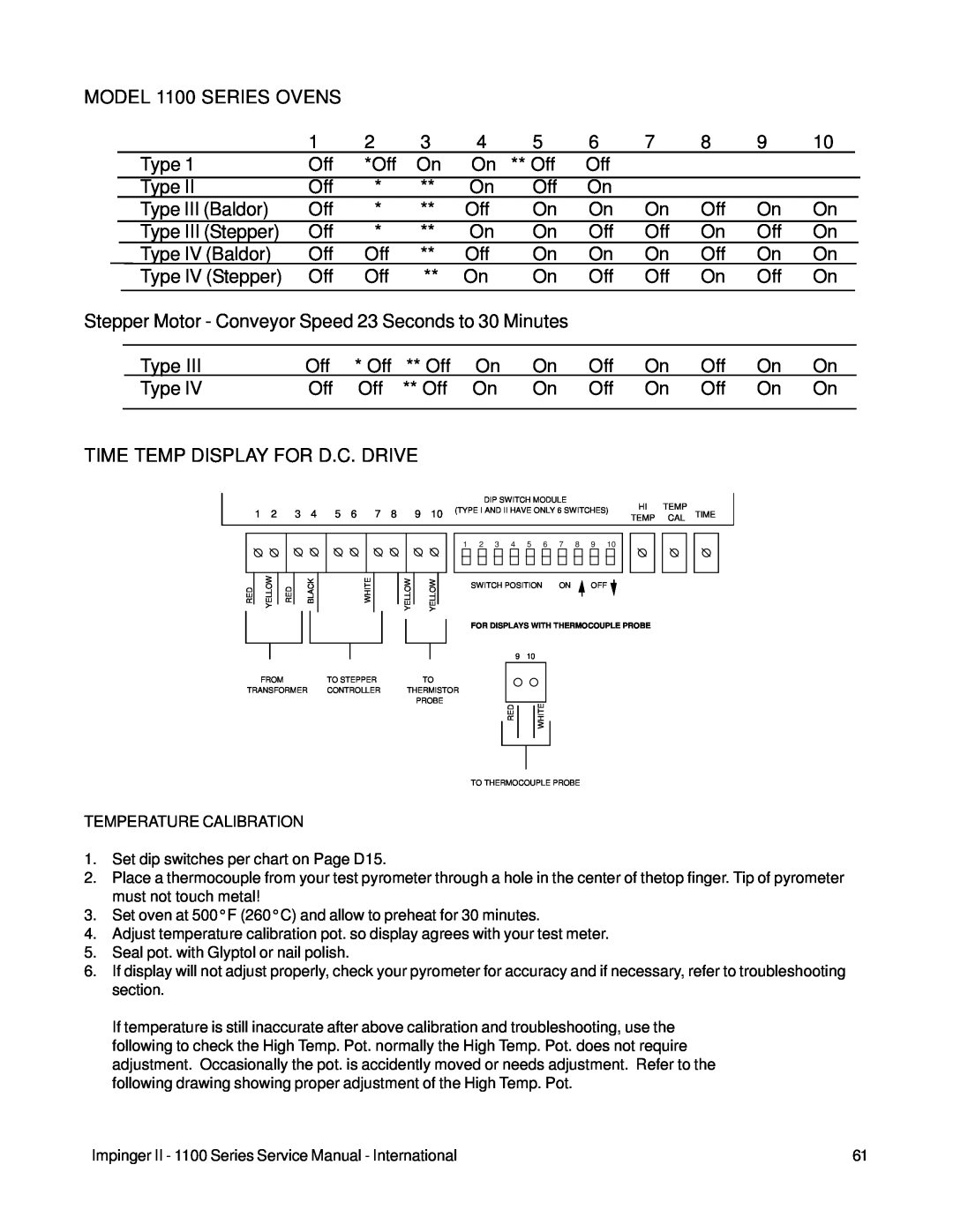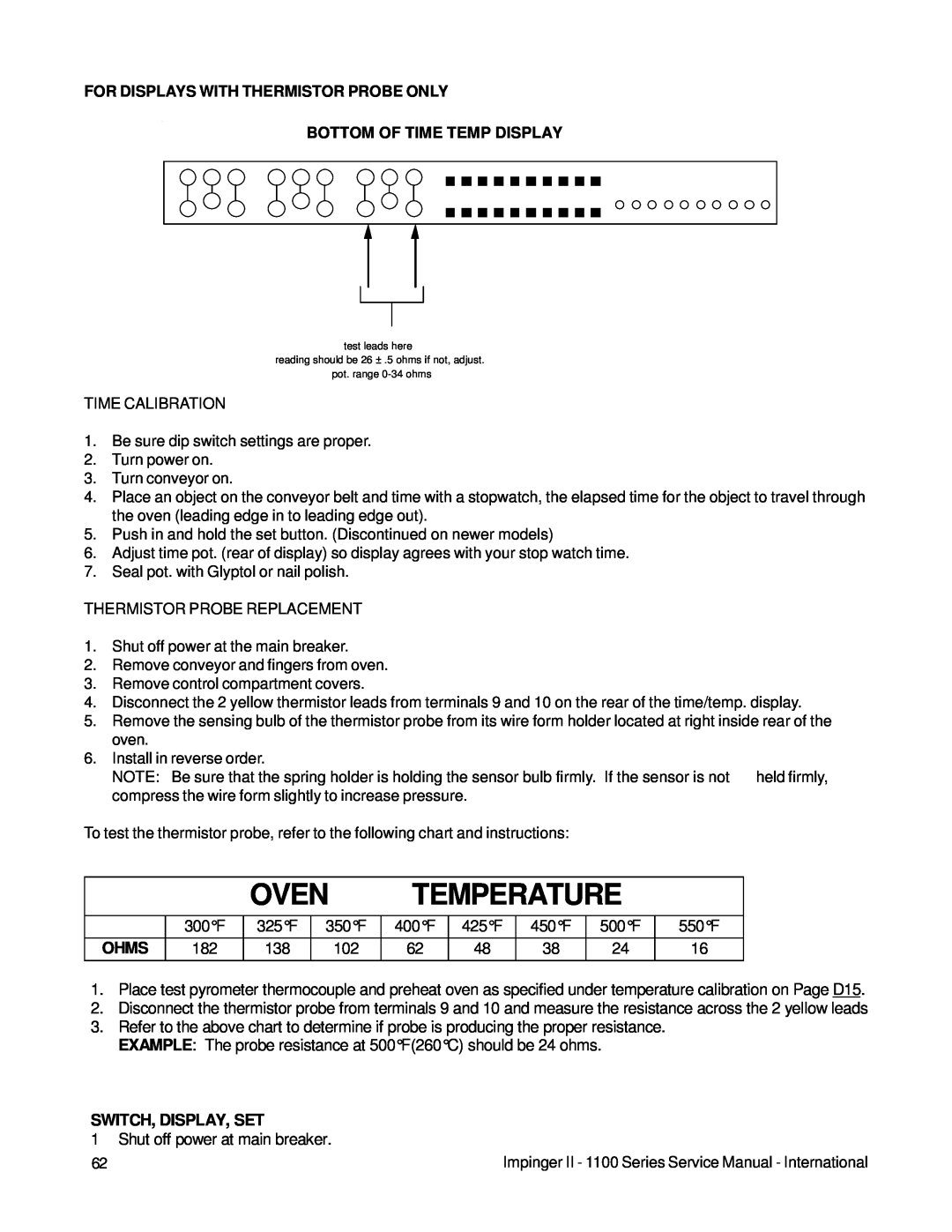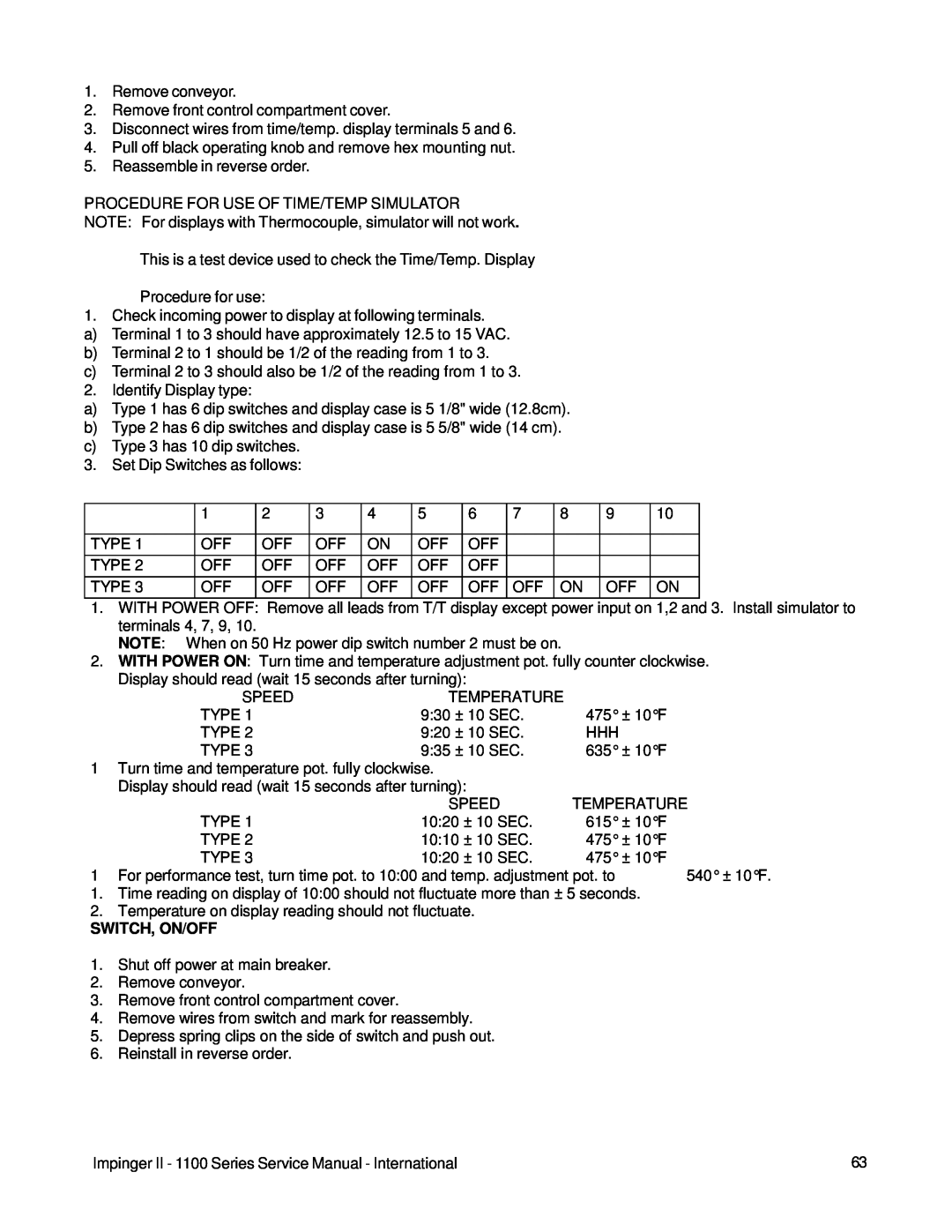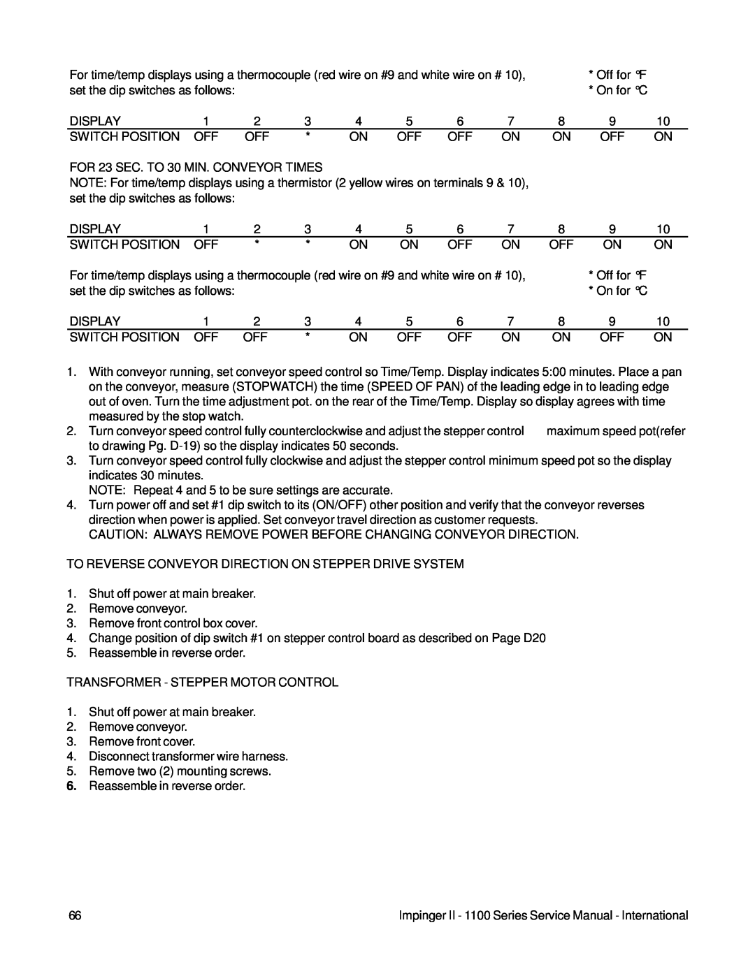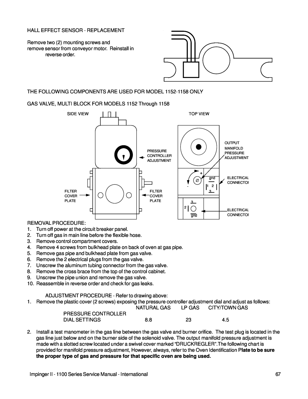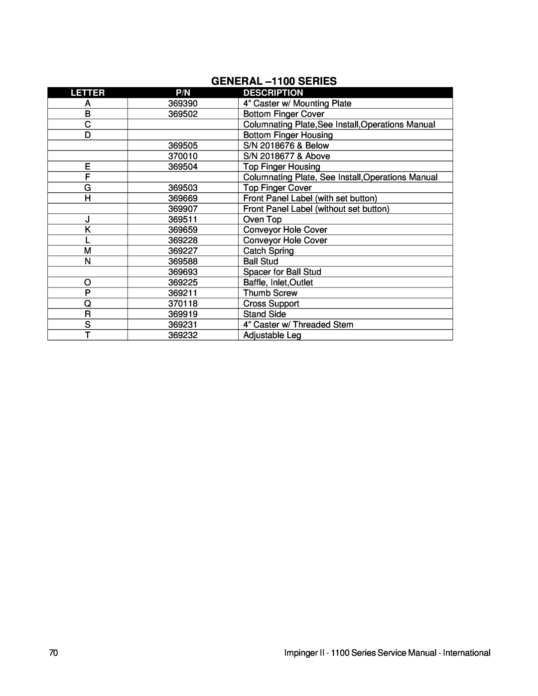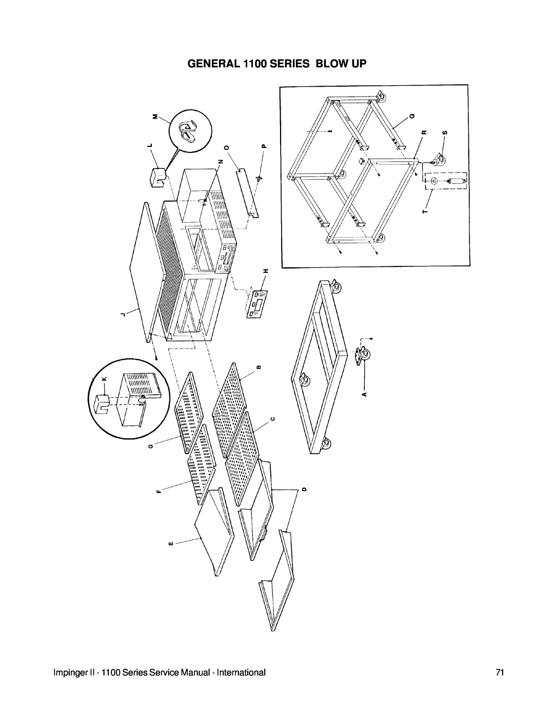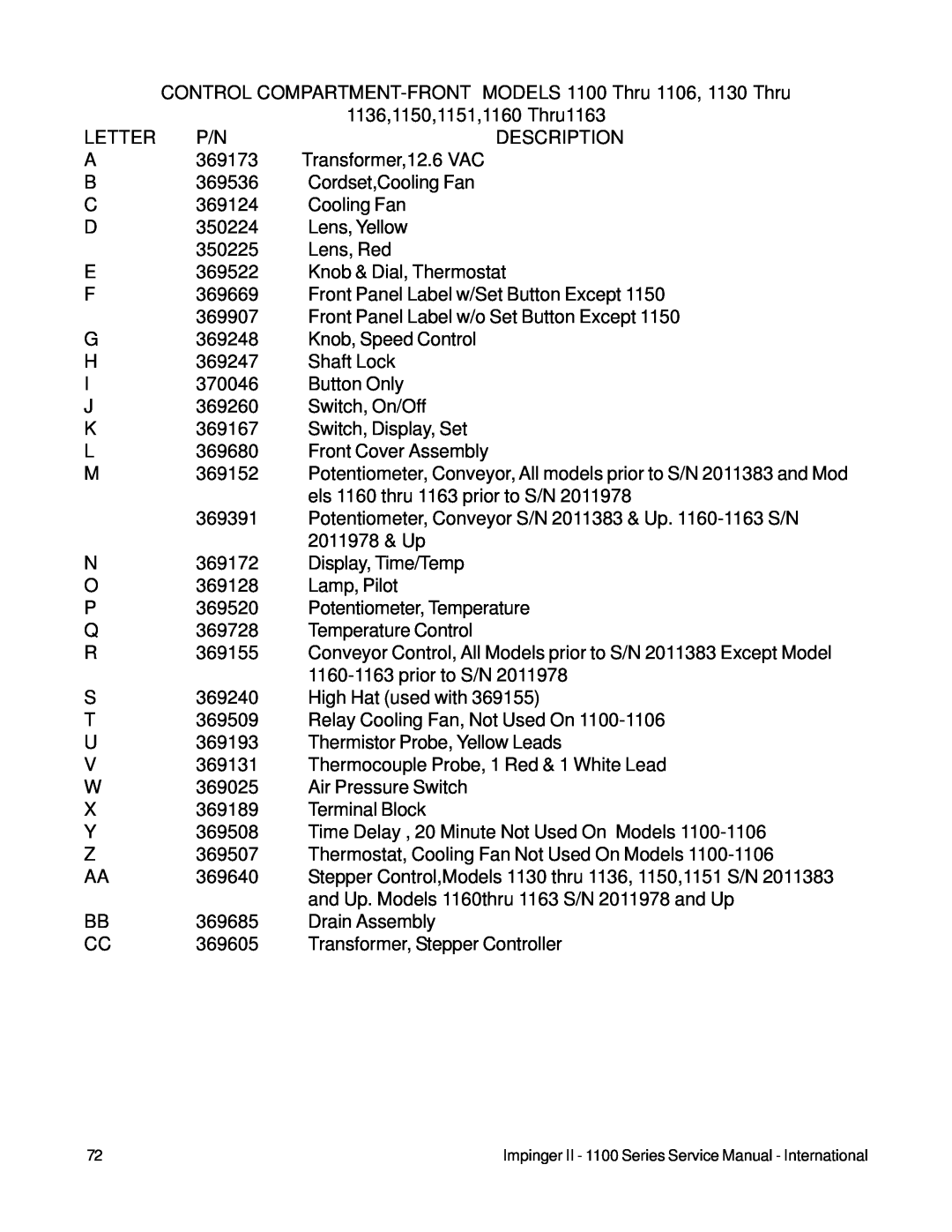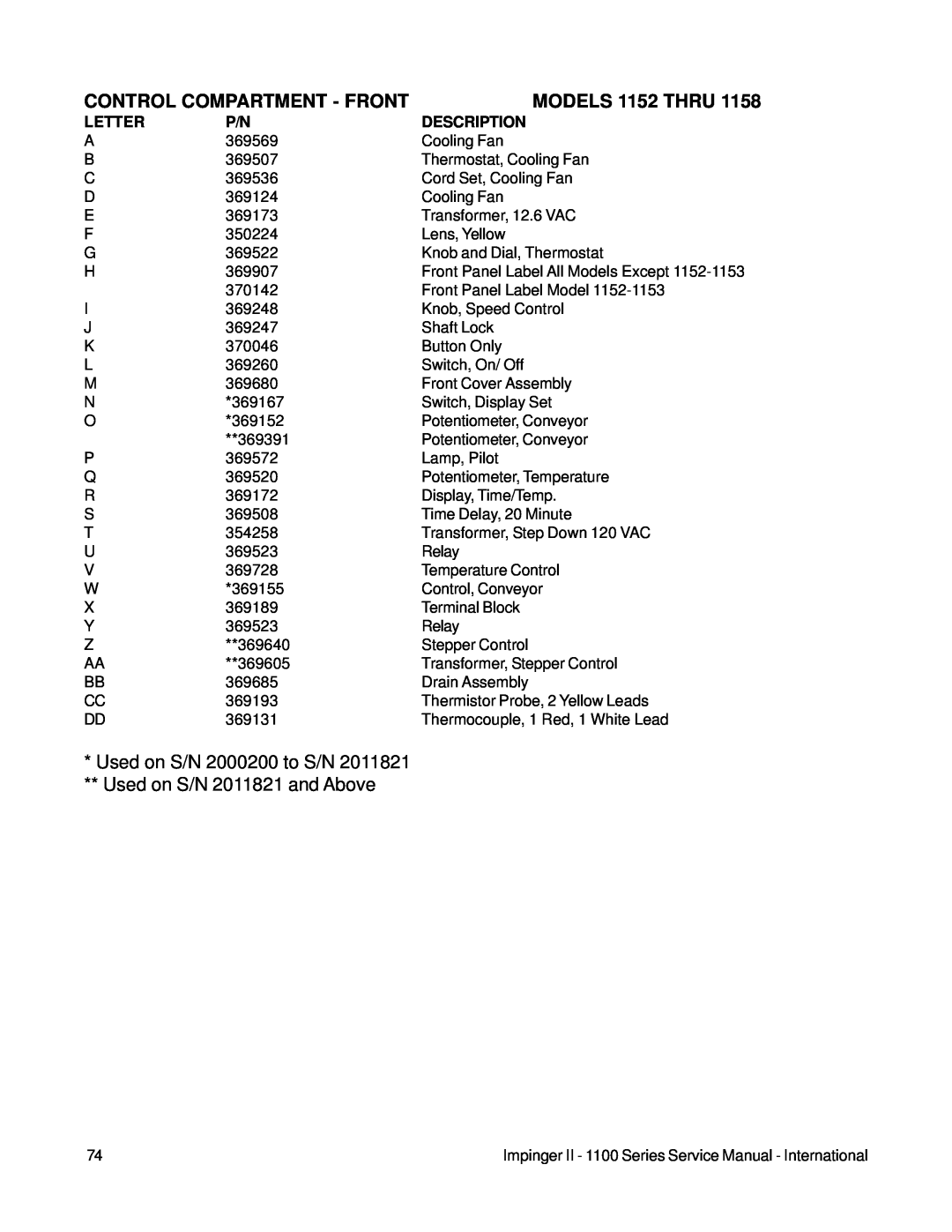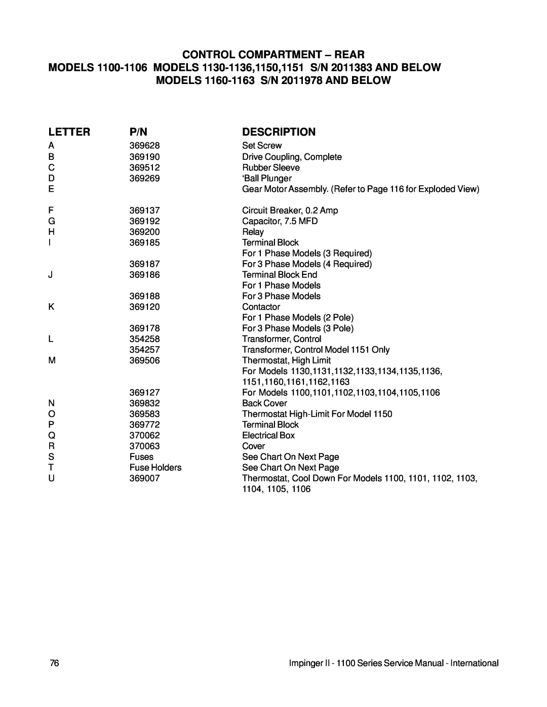
IGNITION CONTROL
1.Shut off power at main breaker.
2.Shut of the gas supply in the main line to the oven.
3.Remove conveyor.
4.Remove the front control compartment cover.
Note: After S/N 2011383 a removable drip tray is located above the ignition control.
5.Disconnect the wires from the ignition control and mark their location for reinstallation.
6.Remove the 4 mounting screws and remove the control.
7.Reassemble in reverse order.
8.Turn on electrical power and gas supply, then check the system for proper operation.
26
27
YELLOW
YELLOW
33
VALVE
VALVE
GND
25 V
25V
GND
BURNER GROUND
L2
NEUTRAL
HSI
120V
HSI
120V
L 1 HOT
11
34
35
32
IGNITION CONTROL
TRANSFORMER, STEP DOWN 24 VAC
1.Shut off power at the main breaker.
2.Remove conveyor.
3.Remove front control compartment cover.
4.Remove wires from transformer and mark for reassembly.
5.Remove 2 mounting screws and replace transformer.
6.Reassemble in reverse order.
BURNER VENTURI
See “Hot Surface Igniter”
HOT SURFACE IGNITER
1.Shut off the electrical power at main breaker.
2.Shut off the gas supply in the main line to the oven.
3.Remove conveyor.
4.Remove rear control compartment cover.
5.Remove Conveyor Motor.
6.Remove electrical plug from the burner cap.
7.Loosen the pipe union in the gas line.
8.Remove 3 screws holding burner cap to burner tube.
9. Pull out on burner cap removing cap and burner venturi.
10.The hot surface igniter is held in place on the burner venturi by a screw, loosen screw and remove igniter.
11.Replace in reverse order.
| NOTE: Care must be used when handling the hot surface igniter as they are quite fragile and may be |
| easily broken if dropped or bumped. |
54 | Impinger II - 1100 Series Service Manual - International |
