22CHAPTER 2: INSTALLING THE ROUTER
■Ethernet cable
■Console cable
■AUX cable
■Power supply, power cord, and chassis ground wire
■Equipment A router
Ethernet
Channel service unit/data service unit (CSU/DSU) or other data communications equipment (DCE) equipment (such as a modem)
Configuration terminal, such as a PC
Mounting the Router The Router 3000 can be mounted onto a vertical surface using two
on a Vertical Surface screws aligned to the brackets on the base of the router. To mount the router on a vertical surface, do the following:
1Mark the bracket positions on the wall.
2Screw two
3Make sure that the front panel LEDs are easily visible to the operator.
4Hang the router on the screws by the two brackets.
5Secure the external power supply of the router to prevent the power cords from detaching.
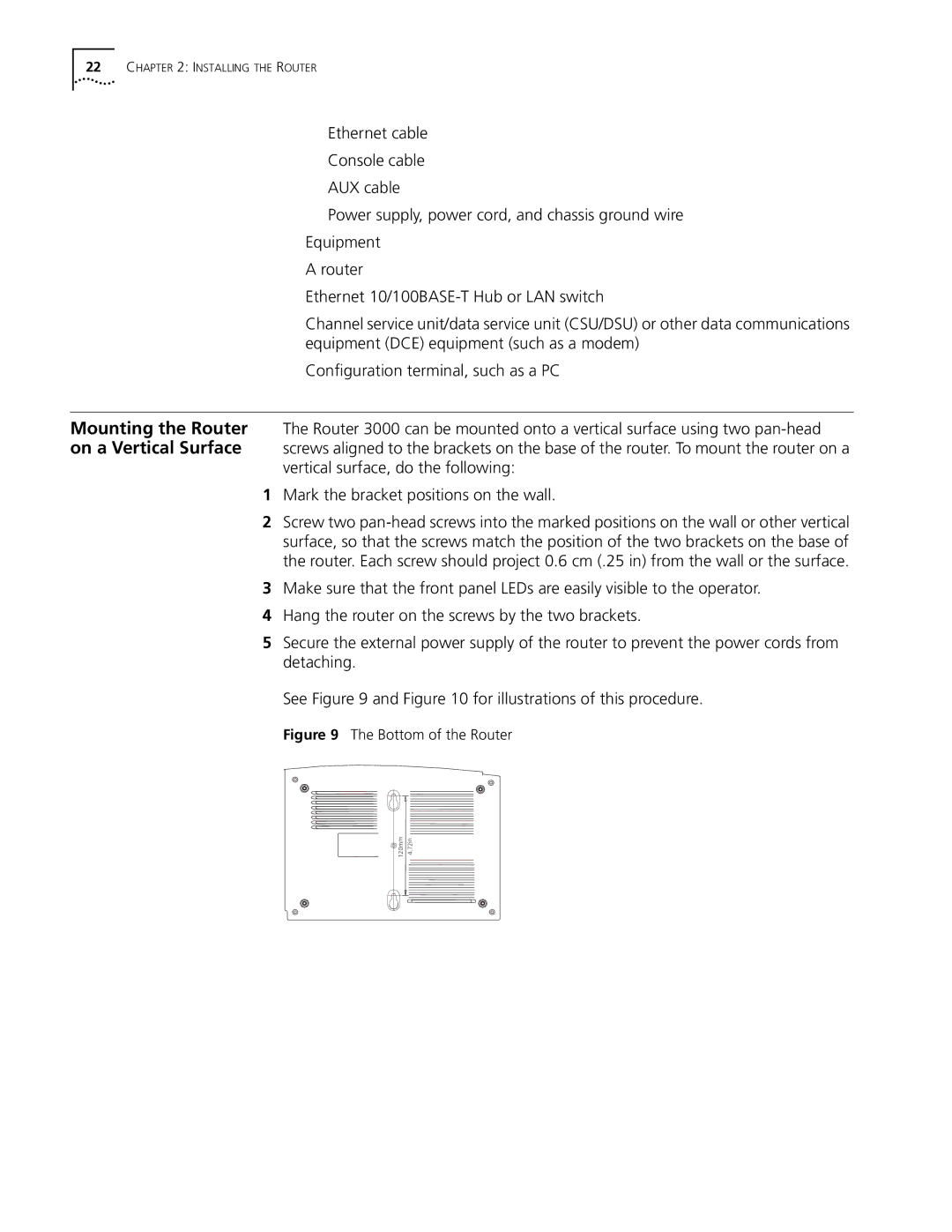
See Figure 9 and Figure 10 for illustrations of this procedure.
Figure 9 The Bottom of the Router
120mm | 72in |
| . |
| 4 |