Connectors and Cables
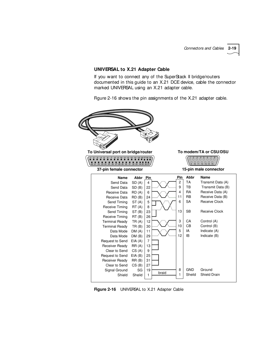
UNIVERSAL to X.21 Adapter Cable
If you want to connect any of the SuperStack II bridge/routers documented in this guide to an X.21 DCE device, cable the connector marked UNIVERSAL using an X.21 adapter cable.
Figure 2-16 shows the pin assignments of the X.21 adapter cable.
To Universal port on bridge/router | To modem/TA or CSU/DSU | ||||||||||||||||||||||||||
1 | 2 | 3 | 4 | 5 | 6 | 7 | 8 | 9 | 10 | 11 12 | 13 | 14 | 15 | 16 17 18 19 | 1 | 2 | 3 | 4 | 5 |
| 6 | 7 | 8 | ||||
20 21 | 22 | 23 24 | 25 | 26 | 27 | 28 29 | 30 | 31 | 32 | 33 | 34 35 | 36 37 | 9 | 10 | 11 | 12 |
| 13 | 14 | 15 |
| ||||||
|
|
|
| ||||||||||||||||||||||||
Name | Abbr |
Send Data | SD (A) |
Send Data | SD (B) |
Receive Data | RD (A) |
Receive Data | RD (B) |
Send Timing | ST (A) |
Receive Timing | RT (A) |
Send Timing | ST (B) |
Receive Timing | RT (B) |
Terminal Ready | TR (A) |
Terminal Ready | TR (B) |
Data Mode | DM (A) |
Data Mode | DM (B) |
Request to Send | EIA (A) |
Receiver Ready | RR (A) |
Clear to Send | CS (A) |
Request to Send | EIA (B) |
Receiver Ready | RR (B) |
Clear to Send | CS (B) |
Signal Ground | SG |
Shield | Sheild |
Pin |
| Pin | Abbr | Name | |
4 |
| 2 | TA | Transmit Data (A) | |
22 |
| 9 | TB | Transmit Data (B) | |
6 |
| 4 | RA | Receive Data (A) | |
24 |
| 11 | RB | Receive Data (B) | |
5 |
| 6 | SA | Receive Clock | |
8 |
|
|
|
| |
23 |
| 13 | SB | Receive Clock | |
26 |
|
|
|
| |
12 |
| 3 | CA | Control (A) | |
30 |
| 10 | CB | Control (B) | |
11 |
| 5 | IA | Indicate (A) | |
29 |
| 12 | IB | Indicate (B) | |
7 |
|
|
|
| |
13 |
|
|
|
| |
9 |
|
|
|
| |
25 |
|
|
|
| |
31 |
|
|
|
| |
27 |
|
|
|
| |
19 | braid | 8 | GND | Ground | |
1 | 1 | Sheild | Shield Drain | ||
|