Contents
SuperStack
3Com Corporation 5400 Bayfront Plaza Santa Clara, California
Contents
Setting UP for Management
PIN-OUTS
Page
About this Guide
Convention Description
Conventions
Icon Description
Documentation documentation
Related
Documentation
3Com recommends that you copy the Docs/referenceguide
Please include the following information when commenting
SuperStack 3 Switch 4900 Series Getting Started Guide
Directory as a whole to maintain the structure of the files
Introducing
Introducing the Superstack 3 Switch 4900 Series
Hardware Features Switches
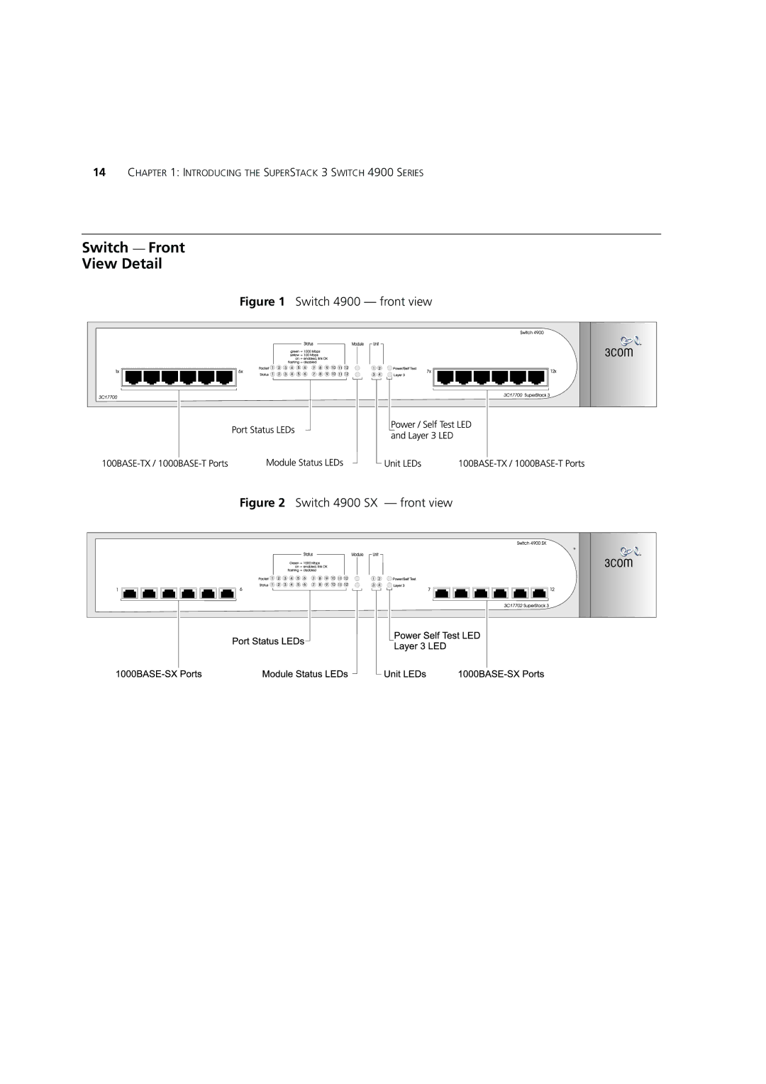
Switch Front View Detail
Switch 4900 front view
Switch 4924 front view
Ports cross-over
Module Status LEDs
Power/Self Test LED
Color Indicates Port Status LEDs
Unit LEDs
Switch Rear
Switch 4900 rear view
Power Socket
Switch 4924 rear view
Switch units, it is returned to these defaults
Default Settings
Supported by your Switch
Installing the Switch
Site
Package Contents
Choosing a Suitable
Desk, or attach it to a wall
Flow through the side panels of the Switch
Rack-mounting
Have been fitted
Repeat steps 2 and 3 for the other side of the Switch
Fitting a bracket for rack-mounting
Interconnecting two Switch 4900 units
Switch
Power-up
Powering-up
Sequence
Power System output
Your Switch
RJ-45 connector is now a grounded port
That contain alignment pins can cause damage to your Switch
Options
Approved Gbic
Switch 4950 Gbic
Operation
Transceivers
Fiber SC connector Type 4 Gbic with internal Eeprom fitted
Inserting a Gbic Transceiver into a Switch
Switch 4950 Gbic Operation
Installing the Switch
Setting UP for Management
Setting Up
Overview
Manual IP Configuration
Automatic IP Configuration
Setting UP for Management
Manually Configuring IP Information
Pre-requisites
Setting Up the Switch with IP Information
Connecting the Workstation to the Switch
Configuring the Workstation with IP Information
Using Command Line Interface via Telnet
Example top-level command line interface menu
Connecting a workstation to the Switch via the console port
19,200 baud Data bits
Setting Up the Switch with IP Information
Automatically
Configured IP
Viewing
Pre-requisites
Viewing IP Information via the Console Port
Example top-level command line interface menu
Refer to Setting Up Command Line Interface Management on
Interface Management
Command Line
Network Using Telnet
CLI Management via
Choosing a Browser
Setting Up Web
Interface
Over the Network
Http//xxx.xxx.xxx.xxx
Passwords
Setting Up Snmp
Default Users
User Default Name Password Access Level
Security Device User Modify operation on the web interface
Problem Solving
For Technical Support information, see Appendix D
Power LED does not light
Solving Problems
Solutions below
On powering-up, the Power/Self Test LED lights yellow
Fan failure warning message is received
Problems
Solving Hardware
For further information about RMON, refer to Status
Error message indicating that the Gbic transceiver is faulty
Unit fails, no Snmp fan failure message is received
Solving Communication Problems
IP Addressing
How do you obtain a registered IP Address?
Safety Information
Important Safety Information
This must be approved for the country where it is used
Important Safety Information
3CGBIC91 Gbic SX 3CGBIC92 Gbic LX
’information de Sécurité Importante
Schko
Appendix a Safety Information
3CGBIC91 Gbic SX 3CGBIC92 Gbic LX
Wichtige Sicherheitsinformationen
Der Netzstecker muß die Norm CEE 7/7 erfüllen Schuko
Wichtige Sicherheitsinformationen
Appendix a Safety Information
Pin to 9-pin
PC-AT Serial Cable
Null Modem Cable 9-pin to RS-232 25-pin
RJ-45 Pin
Connectors
Modem Cable
Assignments
Pin Number 10/100BASE-T 1000BASE-T
Appendix B PIN-OUTS
Power Consumption
Physical Dimensions
Safety
Same unless otherwise stated
Heat Dissipation
Power Supply
Protocols Used for Administration
Standards Supported
Services
Online Technical
Username anonymous
Europe, Middle East and Africa
Asia, Pacific Rim
From this region, email
From this region, enter the URL
Asia, Pacific Rim
Europe, Middle East and Africa
Country Telephone Number Asia, Pacific Rim
Country Telephone Number Latin America
Index
Numbers
Passwords
Regulatory Notices