Manually Configuring IP Information | 41 |
■Documentation supplied with the terminal emulation software.
■A suitable cable:
■A standard null modem cable — if you are connecting directly to the console port, or
■A standard modem cable — if you are connecting to the console port using a modem.
You can find
■You need to have the following so that you can manually set up the Switch with IP information:
■IP address
■subnet mask
■default gateway
Connecting the Workstation to the Switch
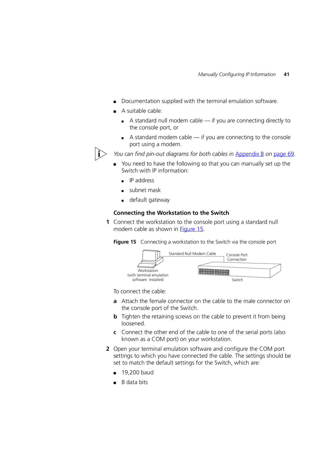
1Connect the workstation to the console port using a standard null modem cable as shown in Figure 15.
Figure 15 Connecting a workstation to the Switch via the console port
To connect the cable:
aAttach the female connector on the cable to the male connector on the console port of the Switch.
bTighten the retaining screws on the cable to prevent it from being loosened.
cConnect the other end of the cable to one of the serial ports (also known as a COM port) on your workstation.
2Open your terminal emulation software and configure the COM port settings to which you have connected the cable. The settings should be set to match the default settings for the Switch, which are: