��������� ������������
Preface
Page
Page
Table of Content
Page
Introduction
Explanation for Model
Nameplate Information
02DD21A0 T 0
Explanation for Series Number
Minimum Mounting Clearances
Preparation for Installation and Wiring
Introduction DD Series
Dimension
ECMD-B9160GMS
Wiring
Wiring Diagram
Wiring/Terminals Setting
Good
Main Circuit Terminal
WiringDD Series
Control Circuit Terminal
Digital Inputs CD, OD, MI1~MI5, COM
Keypad and Start-up
24V
Operation Method
Descriptions of Digital Keypad Outlook
Keypad Descriptions
Parameter Settings
System Parameters
Summary of Parameter Settings
Focpg
Motor Parameters
VFP SVC FOC
NUD
Input/Output Parameters
VFP SVC FOC
Parameter SettingsDD Series
Feedback Parameters
Door Open Parameters
VF VFP SVC FOC FOC
Door Close Parameters
VFP SVC FOC
Protection and Special Parameters
Same time, but without reaction
Phase current detection error cd2
Auto Reset Time for Restart
VFP SVC
Control Parameters
Multi-step Speed Parameter
Communication Parameters
User-defined Parameters
VFP SVC FOC
View User-defined Parameters
System Parameter
Description of Parameter Settings
Software version
Password Input
Password Set
060-07
Control Method
05.08 05.00 05.05 05.07
Door Control Mode
Output Direction
Demo Mode
Source of the Master Frequency Command
Frequency Testing Command
Auto Voltage Regulation AVR Function
Parameter SettingsDD Series
Motor Auto Tuning PM
Full-load Current of motor PM
Rated Power of Motor PM
Rated Speed of PM Motor rpm
Number of Motor Poles PM
Magnetic Pole Re-orientation PM
Motor Auto Tuning IM
Full-load Current of Motor IM
Rated power of Motor IM
Rated speed of IM Motor rpm
Number of Motor Poles IM
Slip Compensation Time Constant
Torque Compensation Time Constant
Torque Compensation Gain
Slip Compensation Gain
Output Voltage 1Base voltage/Motor rated voltage
Output Frequency 1Base frequency /Motor rated frequency
Output Frequency
Output Voltage
Parameter SettingsDD Series Settings 0.00~120.00Hz
Multi-Function Input 2 MI2
Multi-Function Input 1 MI1
Multi-Function Input 3 MI3
Multi-Function Input 4 MI4
Functions Descriptions
Digital Input Operation Direction
Digital Terminal Input Debouncing Time MD-5-13
Multi-function Output Relay1
Multi-function Output Relay2
VF Vfpgsvcfocpg Focpm
Multi-function Output MO3
Digital Output Direction
Position Detection Signal
Position Detection Signal
Encoder pulse
Encoder Input Type Setting
Detection Time for Encoder Feedback Fault
Encoder Feedback Fault Treatment PGF1, PGF2
Encoder Stall and Slip Error Treatment
Door Width Auto-tuning
Door Width Pulses Unit1
Door Open Distance by Initial Speed
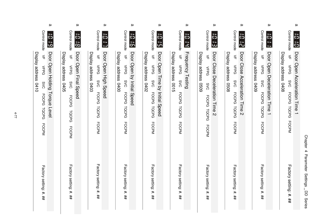
Door Open by Initial Speed
Door Open Time by Initial Speed
Door Open High Speed
Holding Time for OD Open DoorTerminal
Door Open Time-out Setting
Door Open Holding Torque
Door Open DC Brake Time when Stopping
Door Open DC Brake Time when Startup
Door Open Acceleration Time of S1 Curve
Door Open DC Brake Current Level
Door Open DC Brake Starting Frequency
Door Close Distance by Initial Speed
Door Close initial Speed
Door Close Time by Initial Speed
Door Close High Speed
Holding Time for CD Close DoorTerminal
Door Close Time-out Setting
Door Close Holding Torque
Door Close DC Brake Time when Stopping
Door Close DC Brake Time when Startup
Door Close Acceleration Time of S1 Curve
Door Close DC Brake Current Level
Door Re-open Current Level
Door Close DC Brake Starting Frequency
Door Re-open Current Level 1 for Acceleration Area
Door Re-open Current Level 1 for Low Speed Area
Door Re-open Detection Time
Door Close Error Deceleration Time
Software Braking Level
ED Setting of Brake Resistor
Current Boundary
Forward Motor Torque Limit
Emergency/Force Stop Deceleration Method
High Temperature Overheat Warning OH
Low Voltage Level
Action after door re-open/re-close
Door Open/Close Holding Time Before Next Demo
Position Control Mode
Stall Current Level of Position Mode
Clear Demo Mode Door Open/Close Record
Times of Door Opened/Closed in Demo Mode L
Times of Door Opened/Closed in Demo Mode H
Electronic Thermal Overload Relay Selection
Electronic Thermal Characteristic
Auto Reset Time for Restart after Fault
Auto Restart After Fault
Control Parameters
ASR1/ASR2 Width Adjustment
Zero Speed/ASR1 Width Adjustment
Mechanical Gear Ratio
Inertia Ratio
Gain for Speed Feed Forward
Multi-step Speed Parameter
Transmission Speed
Transmission Fault Treatment
Time-out Detection
Communication Protocol
Start Stop Bit Bit character Bit character frame Even
Start Stop
Response message
STX ADR
0FH
Opening door is prohited
Status monitor
Example
Response Delay Time
2nd Output Voltage Mid-point voltage
2nd Output Frequency Mid-point frequency
3rd Output Frequency Mid-point frequency
3rd Output Voltage Mid-point voltage
Frequency Testing
Multi-function Input
Multi-function Input Terminal Direction
~ View User-defined Parameters
Multi-function Output RY1
Multi-function Output RY2
1 B X16 1+11 x160=16+11=27 Enter
View User-defined Parameters
Troubleshooting
Ocd
Over Current oc
GFF
Ground Fault GFF
Over Voltage ov
Low Voltage Lv
Over Heat oH1
Overload oL
Digital Keypad Display is Abnormal
Yes
Phase Loss PHL
Motor is not Running
Fail to Adjust Motor Speed
Motor Stalls during Acceleration
Motor Run Error
13Electromagnetic/Induction Noise
Environmental Condition
Prevent Interfere to Other Machines
High Harmonic at Power Side
Fault Codes and Descriptions
Stop
Common Problems and Solutions
Fault Codes and Descriptions DD Series
Fault Codes and Descriptions DD Series
Fault Codes and Descriptions DD Series
Reset
Check Items Methods and Criterion Period
Maintenance and Inspections
„ Main circuit
„ Resistor of main circuit
„ Cooling fan of cooling system
F, 2 VF+PG, 3 SVC, 4 FOC+PG, 6PM FOC+PG
Control Characteristics
RESET, FWD/REV
Motor Specifications
Appendix B How to Select AC Motor Drive
Capacity Formulas
When one AC motor drive operates one motor
Symbol explanation
Drives Selection
General Precautions
Standard motor
How to Choose a Suitable Motor
Special motors
Motor torque

