5. VENT VALVES
It is recommended that automatic, loose key or screwdriver type vent valves be installed at each convector or radiator.
6. MANIFOLD HEADERS
Split systems with individual supply and return lines from the boiler room should normally have this piping connected to supply and return manifold headers near the boiler. To achieve good water distribution with maximum pressure drop for several circuits, manifolds of at least
The circuits should be spaced on the header at a minimum of 3" (76mm) center to center. Install a balancing cock in each return line.
Manifold headers are recommended for split systems with or without zone valves and also those installations with zone circulators. If the system is to be split at remote points, good practice requires special attention be given to main pipe sizing to allow balancing of water flow.
The boiler piping system of a hot water boiler connected to heating coils located in air handling units where they may be exposed to refrigerated air circulation must be equipped with flow control valves or other automatic means to prevent gravity circulation of the boiler water during the cooling cycle.
7. COOLING PIPING
When the boiler is used in conjunction with a refrigeration system it must be installed so that the chilled medium is piped in parallel with the boiler with appropriate valves to prevent the chilled medium from entering the boiler, see Figure 13.
Water temperature in the heating system must be reduced to less than 1000F (38°C) before cooling system is started, or damage to the chiller unit may occur.
SCHEMATIC SHOWING PROPER PIPING ISOLATION
OF THE BOILER FROM THE CHILLER
FIGURE 13.
If the boiler is connected to chilled water piping or its heating coils are exposed to refrigerated air, the boiler piping system must be equipped with flow valves or other automatic means to prevent gravity circulation through the boiler during the cooling cycle.
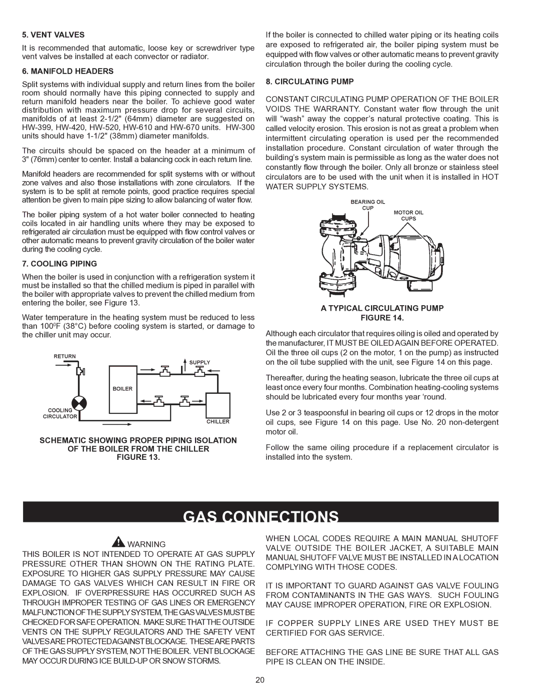
8. CIRCULATING PUMP
CONSTANT CIRCULATING PUMP OPERATION OF THE BOILER VOIDS THE WARRANTY. Constant water flow through the unit will “wash” away the copper’s natural protective coating. This is called velocity erosion. This erosion is not as great a problem when intermittent circulating operation is used per the recommended installation procedure. Constant circulation of water through the building’s system main is permissible as long as the water does not constantly flow through the boiler. Only all bronze or stainless steel circulators are to be used with the unit when it is installed in HOT WATER SUPPLY SYSTEMS.
A TYPICAL CIRCULATING PUMP
FIGURE 14.
Although each circulator that requires oiling is oiled and operated by the manufacturer, IT MUST BE OILED AGAIN BEFORE OPERATED. Oil the three oil cups (2 on the motor, 1 on the pump) as instructed on the oil tube supplied with the unit, see Figure 14 on this page.
Thereafter, during the heating season, lubricate the three oil cups at least once every four months. Combination
Use 2 or 3 teaspoonsful in bearing oil cups or 12 drops in the motor oil cups, see Figure 14 on this page. Use No. 20
Follow the same oiling procedure if a replacement circulator is installed into the system.
GAS CONNECTIONS
WARNING | WHEN LOCAL CODES REQUIRE A MAIN MANUAL SHUTOFF | |
VALVE OUTSIDE THE BOILER JACKET, A SUITABLE MAIN | ||
THIS BOILER IS NOT INTENDED TO OPERATE AT GAS SUPPLY | ||
MANUAL SHUTOFF VALVE MUST BE INSTALLED IN A LOCATION | ||
PRESSURE OTHER THAN SHOWN ON THE RATING PLATE. | ||
COMPLYING WITH THOSE CODES. | ||
EXPOSURE TO HIGHER GAS SUPPLY PRESSURE MAY CAUSE | ||
| ||
DAMAGE TO GAS VALVES WHICH CAN RESULT IN FIRE OR | IT IS IMPORTANT TO GUARD AGAINST GAS VALVE FOULING | |
EXPLOSION. IF OVERPRESSURE HAS OCCURRED SUCH AS | FROM CONTAMINANTS IN THE GAS WAYS. SUCH FOULING | |
THROUGH IMPROPER TESTING OF GAS LINES OR EMERGENCY | MAY CAUSE IMPROPER OPERATION, FIRE OR EXPLOSION. | |
MALFUNCTIONOFTHESUPPLYSYSTEM,THEGASVALVESMUSTBE |
| |
CHECKEDFORSAFEOPERATION. MAKESURETHATTHEOUTSIDE | IF COPPER SUPPLY LINES ARE USED THEY MUST BE | |
VENTS ON THE SUPPLY REGULATORS AND THE SAFETY VENT | CERTIFIED FOR GAS SERVICE. | |
VALVESAREPROTECTEDAGAINSTBLOCKAGE. THESEAREPARTS |
| |
OFTHE GAS SUPPLYSYSTEM, NOTTHE BOILER. VENTBLOCKAGE | BEFORE ATTACHING THE GAS LINE BE SURE THAT ALL GAS | |
MAY OCCUR DURING ICE | PIPE IS CLEAN ON THE INSIDE. |
20