Tennessee Waltz Parkway Ashland City, TN
Models HW 300, 399, 420, 520, 610
Important Definitions
Safe INSTALLATION, USE and Service
General Safety
Table of Contents
Propane Natural
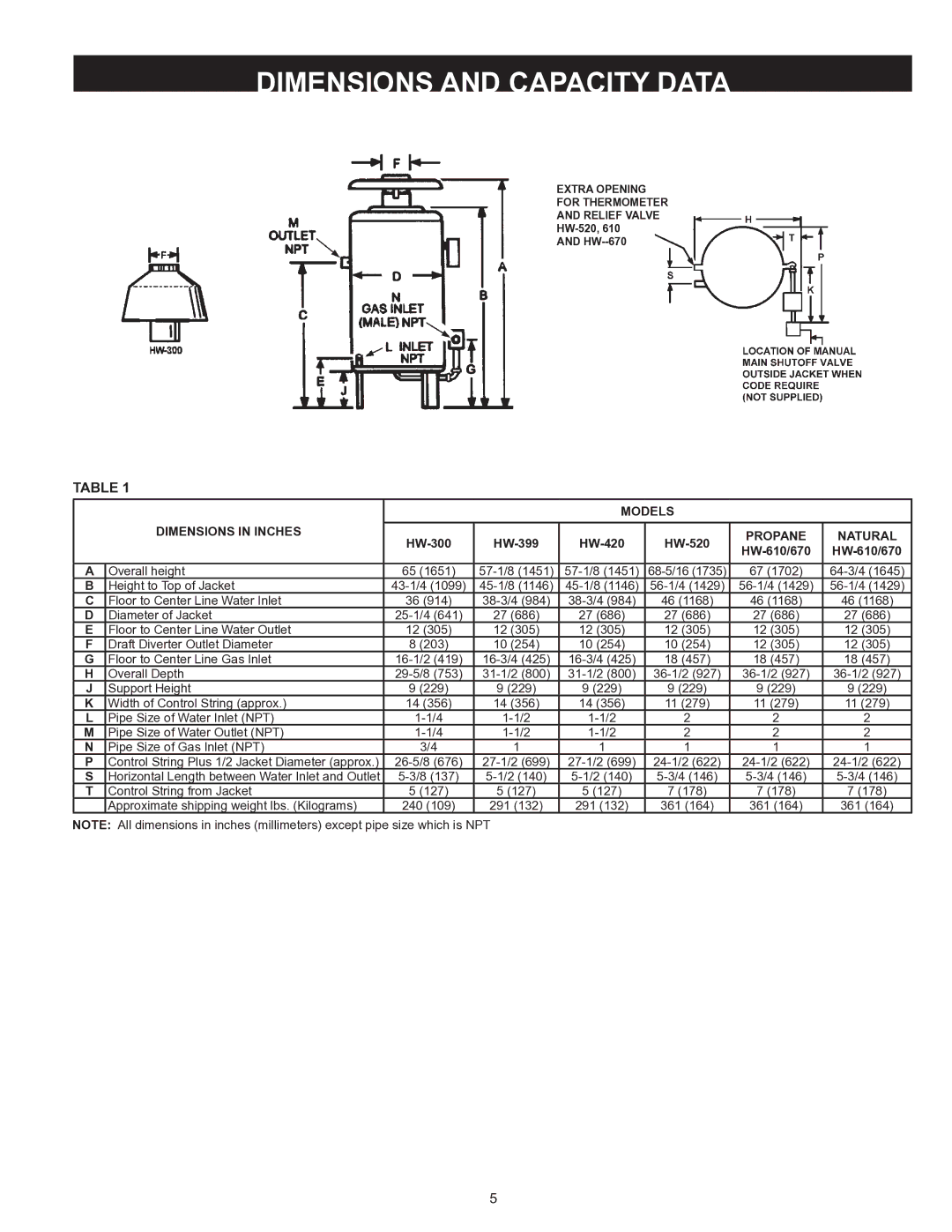
Dimensions and Capacity Data
27.7 33.3
Recovery Capacities
LIQUefied petroleum gas models
High Altitude Installations
Introduction
Controls and Function
High Limit Switch Safety Flow Switch
Manual Reset High Limit
Thermal Balancer
GPM LPM
Safety Relief Valves
Tank Temperature Control
Thermometers
General
Drain Valve Not Supplied
Required Ability
Canadian Installations
Confined Space S. Installations
AIR Requirements
Unconfined Space
Typical Boiler Installation
Installation Clearances
Venting
Leveling
Connecting Boiler to a Common Vent
Vent Pipe Installation
Draft Hood
Vent Connection
Venting System
Venting Sidewall Optional Power Vent System
Multiple Vent Table
Model HW-300 Boiler
Combined Vent Sizing Tables
Conventional Installations
System Installations
LINEAR-TEMP Installations
ONE Boiler Installed Independent of the Primary System
Schematic of the LINEAR-TEMPSYSTEM
NO. Suggested Items for Installation
Boiler Inlet Outlet Sizes
Minimum Branch Sizes to Boilers
GAS Connections
Correct GAS
Purging and Sizing
Specific Multiplier Gravity
Example
GAS Pressure Regulators
Model Rated Manifold Pressure Number Input Natural Propane
Wiring Connections
Wiring
D. System
HW 300 to
Single Stage I.I.D. Honeywell GAS Valve
HW 300 thru 670. Natural and Propane GAS U.S. & Canada
LINEAR-TEMP Installations
Boilers and Secondary Circulator are Controlled by
Page
MODELS, Jucntion BOX W/4 Terminals
Canadian MODELS, Junction BOX W/6 Terminals
Canadian MODELS, Junction BOX W/6 Terminals
Schematic
MODELS, Junction BOX W/4 Terminals
MODELS, Junction BOX W/4 Terminals
Piping
Wiring Figures 16 and 17 on Pages 24
Commercial Boiler with Vertical Tank
USE this Table for Correct Pump and Water Pipe Size
Commercial Boiler with Horizontal Tank
Commercial Boiler with Vertical TANK, CER-TEMP
Wiring Figures 21 to 27 on Pages 28 to
HW-300 HW-399 HW-420 HW-520
Three HW-520s, HW-610s or HW-670s UP-FLOW Model
USE this Table for Correct Pump and Water Pipe Size
Filling the System
Operation and START-UP Instructions
Pilot and Main Burner
Main Burner
Pilot Burner Electronic Ignition
Refer to Operating at Full Input or Full Capacity
Checking and Adjusting the Input
Consumption Rate
Stage Main Burner Operation Flame Current Sensed
For Your Safety Read Before Lighting
URN Pilo T Firing VA LVE Counterclockwise
SET T HE Thermostat to Lowwest Setting
Relief Valve
General Maintenance
Manual Reset High Limit Switch Continuity Test
PRE-TROUBLESHOOTING
Cleaning and Flushing Instructions
HOT Water Supply Boilers Preventive Maintenance
Internal Contaminants
CER-TEMP 80 Recovery System Checkout Procedure
Troubleshooting
YES
Is ceramic insulator surrounding the electrode in good
Burner ignition problems?
Condition not cracked or broken?
Is there excessive draft conditions that may cause pilot
MV & MV/PV?
Replace pilot burner assembly
Location of LEDs Flame LED Yellow
LED Status and Troubleshooting
Status LED Green
OFF
No Call for Heat Not applicable None
OFF
Conditions and Exceptions
Limited Warranty