INSTALLATION INSTRUCTIONS
ASSEMBLE MOTOR
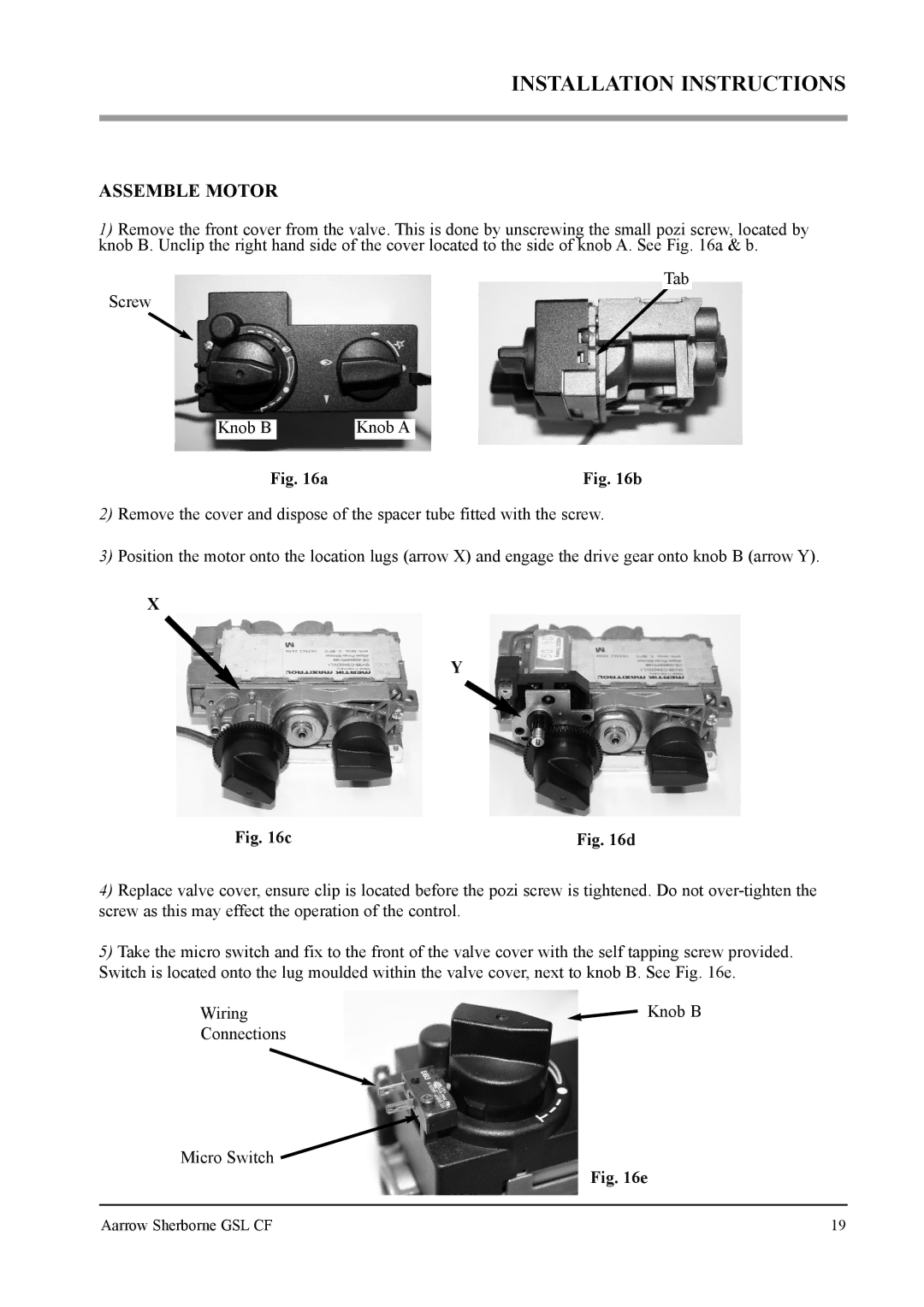
1)Remove the front cover from the valve. This is done by unscrewing the small pozi screw, located by knob B. Unclip the right hand side of the cover located to the side of knob A. See Fig. 16a & b.
Tab
Screw
Knob B | Knob A |
Fig. 16a | Fig. 16b |
2)Remove the cover and dispose of the spacer tube fitted with the screw.
3)Position the motor onto the location lugs (arrow X) and engage the drive gear onto knob B (arrow Y).
X
Y
Fig. 16c | Fig. 16d |
4)Replace valve cover, ensure clip is located before the pozi screw is tightened. Do not
5)Take the micro switch and fix to the front of the valve cover with the self tapping screw provided. Switch is located onto the lug moulded within the valve cover, next to knob B. See Fig. 16e.
Wiring | Knob B |
Connections
Micro Switch ![]()
Fig. 16e
Aarrow Sherborne GSL CF | 19 |
