SERVICING
Step 7 Clear inside of stove of any debris.
Step 8 To
Note:When relocating the body and canopy assembly ensure the front location tab is engaged in the chassis.
BURNER AND VALVE
ASSEMBLY REMOVAL
Please note! When handling the burner assembly be aware of the sharp points of the self tapping screws on the underside
Ensure the appliance is cold.
Step 1 Isolate the gas supply from the stove
Step 2 Disconnect the supply inlet pipe by releasing the pipe nut at the rear of the valve, see page 13.
Step 3 Remove the outer body of the stove (Ref Page 25).
Step 4 Remove the dummy fuel retainer and then the glass frame assembly (Ref Page 25).
Step 5 Remove the coals or logs.
Step 6 Remove the base coal matrix (four pieces) Take care not to damage the matrix, (Page 14).
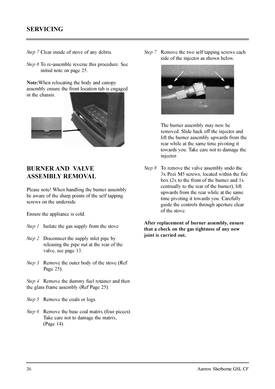
Step 7 Remove the two self tapping screws each side of the injector as shown below.
The burner assembly may now be removed. Slide back off the injector and lift the burner assembly upwards from the rear while at the same time pivoting it towards you. Take care not to damage the injector.
Step 8 To remove the valve assembly undo the 3x Pozi M5 screws, located within the fire box (2x to the front of the burner and 1x centrually to the rear of the burner), lift upwards from the rear while at the same time pivoting it towards you. Carefully guide the controls through aperture clear of the stove.
After replacement of burner assembly, ensure that a check on the gas tightness of any new joint is carried out.
26 | Aarrow Sherborne GSL CF |