INSTALLATION INSTRUCTIONS
PREPARATION OF THE STOVE
Prior to starting the installation and after removing the packaging, check that all the parts have been supplied to the contents list on page 5.
Carry out the following:-
Step 1 Remove outer casing (disengage locking levers see page 25, steps 1a /b, 2, 3, 4, and 5). Step 2 Remove glass and retaining frame (see page 25 step 6).
Step 3 Remove the packaging from the coal / log set and cut the cable tie retaining 8mm olive and valve connection nut (located to the rear of valve assem- bly).
STOVE LOCATION
The appliance must not be installed in a room or space, which contains a bath or shower.
This stove is designed for use with either top or rear flue outlets and must be mounted on a hearth. The hearth must be strong enough to support the stove. For overall minimum hearth sizes see Fig.4a and Fig.4b.
To comply with current Building Regulations the stove must stand on a fireproof hearth which has a minimum upper fireproof layer of 12mm
The hearth must not be capable of inadvertent covering by a carpet or rug. This should be achieved by either:
•The hearth being 50mm above the level of the room floor.
or •a 50mm high fender or kerb being fixed around the edge of the hearth.
Ensure the hearth is level and flat.
Do not place any combustible material including clothing, furniture and furnishings (including curtains) within 1 metre of the stove.
For details of combustible and
It is acceptable to place the stove against plaster board on dry line property.
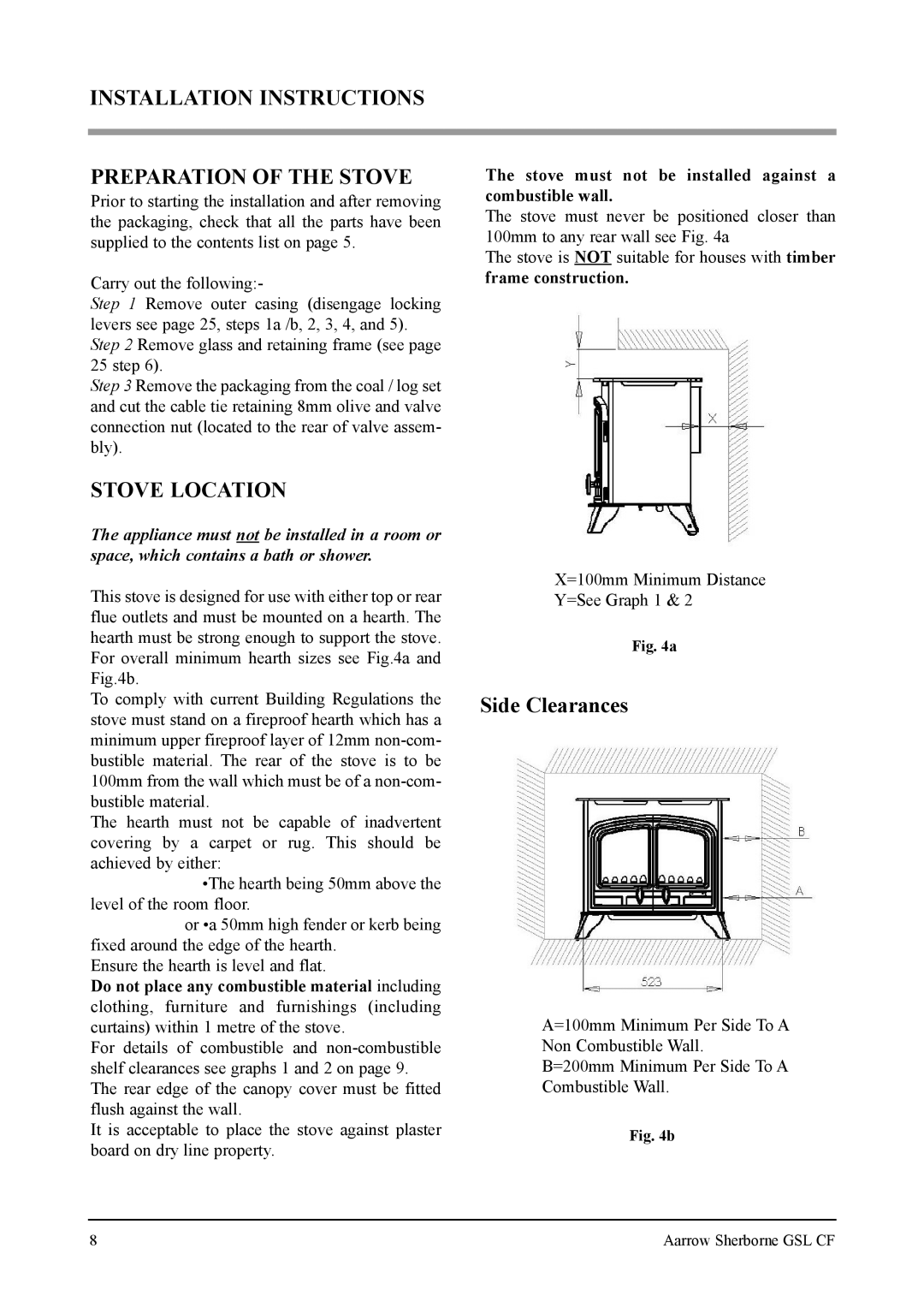
The stove must not be installed against a combustible wall.
The stove must never be positioned closer than 100mm to any rear wall see Fig. 4a
The stove is NOT suitable for houses with timber frame construction.
X=100mm Minimum Distance
Y=See Graph 1 & 2
Fig. 4a
Side Clearances
A=100mm Minimum Per Side To A
Non Combustible Wall.
B=200mm Minimum Per Side To A
Combustible Wall.
Fig. 4b
8 | Aarrow Sherborne GSL CF |