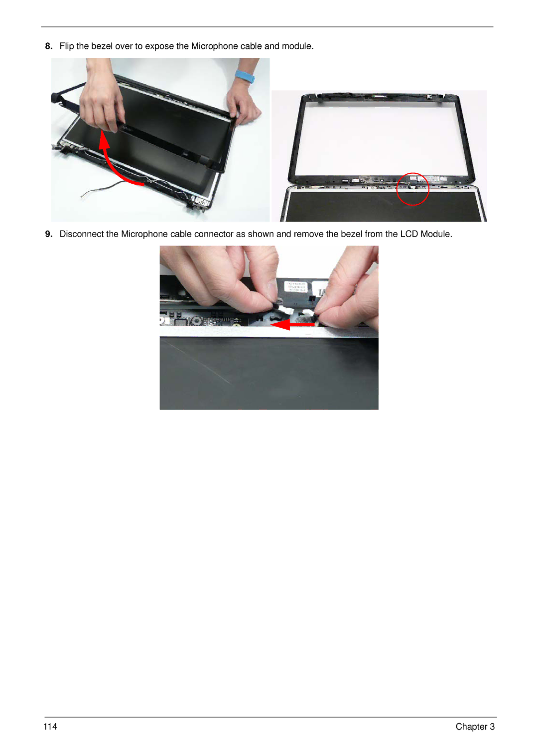
Manuals
/
Brands
/
Computer Equipment
/
Laptop
/
Acer
/
Computer Equipment
/
Laptop
Acer
8940
- page 124
1
124
280
280
Download
280 pages, 9.5 Mb
114
Chapter 3
8.
Flip the bezel over to expose the Microphone cable and module.
9.
Disconnect the Microphone cable connector as shown and remove the bezel from the LCD Module.
Contents
Main
Page
Copyright
Disclaimer
Conventions
Preface
Page
System Specifications 1
System Utilities 31
Machine Disassembly and Replacement 49
Page
Troubleshooting 191
Jumper and Connector Locations 207
FRU (Field Replaceable Unit) List 211
Page
System Specifications
Chapter 1
Features
Dimensions and Weight
Communication
Privacy control
Power subsystem
Special keys and controls
Environment
4Chapter 1
System Block Diagram
P8.9.10.11.12.13
UP61111AQDD
PCIE-1
Bluetooth
Your Acer Notebook tour
Front View
Page
Closed Front View
Rear View
Left View
Right View
Bottom View
TouchPad Basics
Using the Keyboard
Key Types
Windows Keys
System Hotkeys
Using the System Utilities
Acer GridVista (dual-display compatible)
Hardware Specifications and Configurations
Page
Page
Page
Page
Chapter 1 21
Hard Disk Drive Interface) Item Specification
22 Chapter 1
Chapter 1 23
24 Chapter 1
Page
Page
Page
Page
Page
Page
System Utilities
Chapter 2
BIOS Setup Utility
Navigating the BIOS Utility
Information
Main
Security
Setting a Password
Removing a Password
Changing a Password
Boot
Exit
BIOS Flash Utilities
DOS Flash Utility
Page
Page
Remove HDD/BIOS Password Utilities
Page
Page
Using DMITools
Read DMI Information from Memory
Write Product Name to EEPROM
Write Serial Number to EEPROM
4). Write UUID to EEPROM (Create UUID from Intel WFM20.pdf)
Using the LAN MAC EEPROM Utility
Page
Machine Disassembly and Replacement
Chapter 3
Disassembly Requirements
General Information
Pre-disassembly Instructions
Disassembly Process
External Module Disassembly Process
External Modules Disassembly Flowchart
Page
Page
Page
Page
Page
Page
Page
Page
Page
Page
Page
Page
Page
Page
Page
Main Unit Disassembly Process
Upper Cover Disassembly Flowchart
Lower Cover Disassembly Flowchart
Page
Page
Removing the Switch Cover
Page
Page
Page
Page
Page
Removing the Upper Cover
Page
Page
Page
Page
Page
Page
Page
Page
Page
Page
Page
Page
Page
Page
Page
Page
Page
Page
Page
Page
Page
Page
Page
Page
Page
Page
Page
Page
Page
Removing the Thermal Module
Removing the Graphics Card Heatsink
Page
Page
LCD Module Disassembly Process
Standard Bezel LCD Module Disassembly Flowchart
Removing the Standard LCD Bezel
Page
Page
Removing the LCD Panel
Page
Page
Page
Page
Flush Bezel LCD Module Disassembly Flowchart
Page
Page
Removing the Flush LCD Bezel
Page
Removing the LCD Panel
Page
Page
Page
Page
LCD Module Reassembly Procedure
Standard Bezel LCD Module ReassemblyLCD Panel
Page
Page
Page
Page
Page
Page
Page
Page
Page
Page
Page
Page
Page
Page
Page
Replacing the Graphics Card Heatsink
Replacing the Thermal Module
Page
Page
Replacing the Subwoofer
Page
Page
Page
Page
Page
Page
Page
Page
Page
Page
Page
Page
Page
Page
Page
Page
Page
Page
Page
Page
Page
Replacing the Upper Case
Page
Page
Replacing the LCD Module
Page
Page
Page
Page
Page
Page
Page
Page
Page
Page
Page
Page
Page
Page
Page
Troubleshooting
Chapter 4
Common Problems
Power On Issue
Computer Shuts down Intermittently
No Display Issue
No POST or Video
Abnormal Video Display
Random Loss of BIOS Settings
Chapter 4 195
LCD Failure
Built-In Keyboard Failure
Chapter 4 197
TouchPad Failure
Internal Speaker Failure
Sound Problems
Internal Microphone Failure
Microphone Problems
HDD Not Operating Correctly
USB (Right Up/Down Side) Failure
Other Failures
Intermittent Problems
Undetermined Problems
Post Codes
Chipset POST Codes
Page
Page
Page
Jumper and Connector Locations
Chapter 5
Top View
Bottom View
Clearing Password Check and BIOS Recovery
Clearing Password Check
BIOS Recovery by Crisis Disk
BIOS Recovery Boot Block:
BIOS Recovery Hotkey:
Steps for BIOS Recovery by USB flash crisis disk:
FRU (Field Replaceable Unit) List
Chapter 6
Aspire 8940 Exploded Diagrams
Main Chassis
LCD Assembly
Aspire 8940 FRU List
Page
Page
Page
Page
Page
Page
Page
Screw List
Page
Model Definition and Configuration
Appendix A
Aspire 8940 Series
Page
Page
Page
Page
Page
Page
Page
Page
Page
Page
Page
Page
Page
Page
Test Compatible Components
Appendix B
Microsoft Windows 7 Environment Test
Page
Page
Page
Page
Page
Page
Page
Page
Page
Page
Page
Page
Page
Page
Page
Page
Page
Page
Page
Page
Page
Page
Page
Page
Online Support Information
Appendix C
Page
Index
A
B
K
C
L
M
N
O
P
T
U
V
W