Removing the Upper Cover
IMPORTANT: The TouchPad is supplied as part of the Upper Cover. If the TouchPad is defective, replace the entire Upper Cover.
1.See “Removing the LCD Module” on page 74.
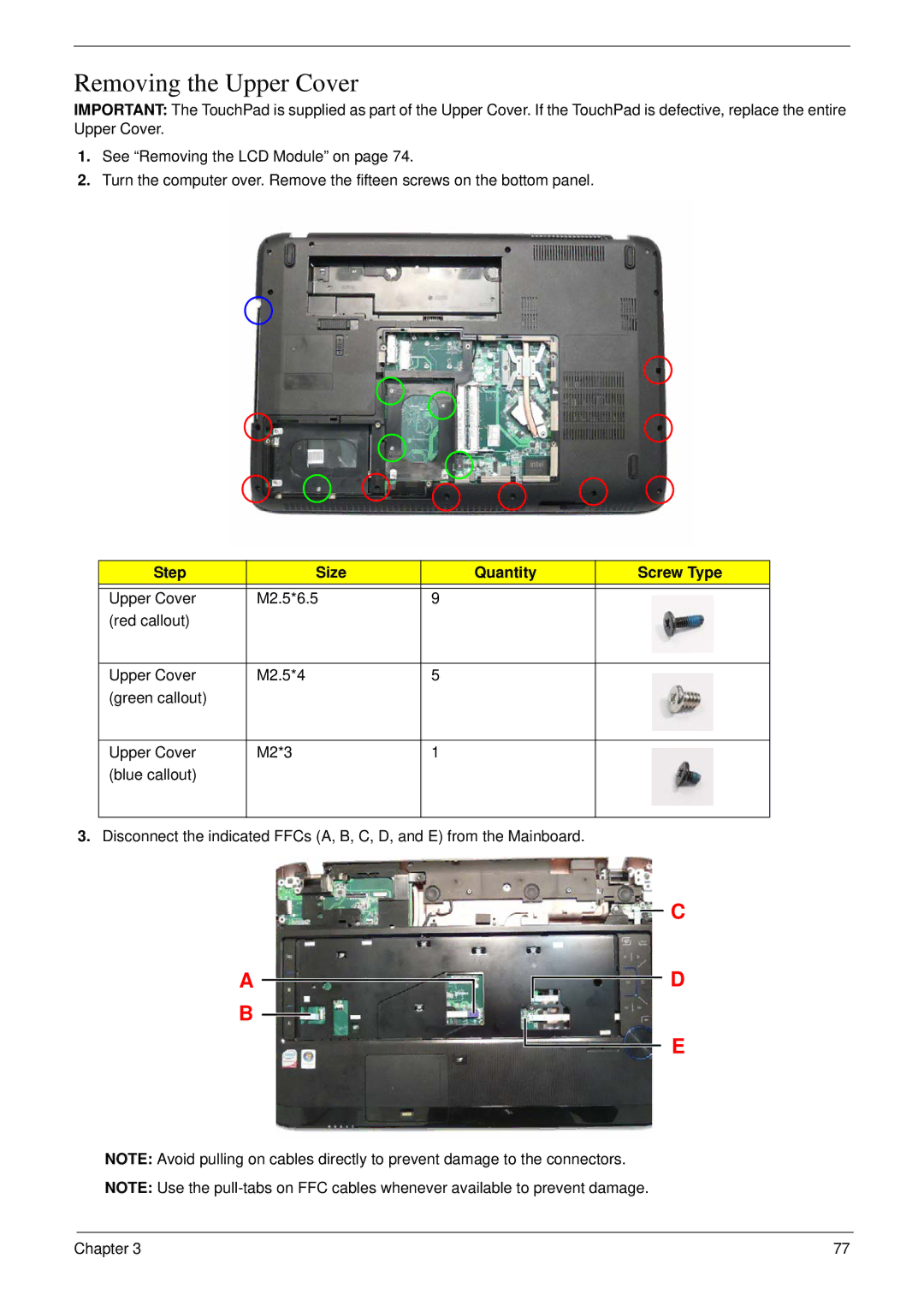
2.Turn the computer over. Remove the fifteen screws on the bottom panel.
Step | Size | Quantity | Screw Type |
|
|
|
|
Upper Cover | M2.5*6.5 | 9 |
|
(red callout) |
|
|
|
|
|
|
|
Upper Cover | M2.5*4 | 5 |
|
(green callout) |
|
|
|
|
|
|
|
Upper Cover | M2*3 | 1 |
|
(blue callout) |
|
|
|
|
|
|
|
3.Disconnect the indicated FFCs (A, B, C, D, and E) from the Mainboard.
A B
C
D
E
NOTE: Avoid pulling on cables directly to prevent damage to the connectors.
NOTE: Use the
Chapter 3 | 77 |