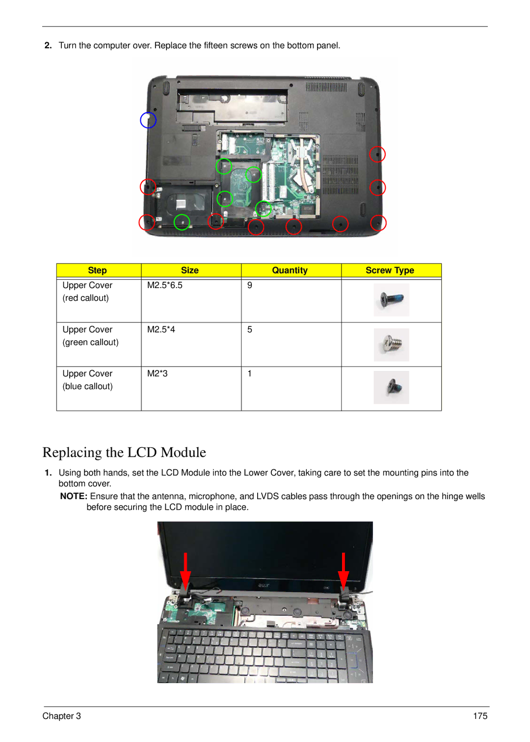
2.Turn the computer over. Replace the fifteen screws on the bottom panel.
Step | Size | Quantity | Screw Type |
|
|
|
|
Upper Cover | M2.5*6.5 | 9 |
|
(red callout) |
|
|
|
|
|
|
|
Upper Cover | M2.5*4 | 5 |
|
(green callout) |
|
|
|
|
|
|
|
Upper Cover | M2*3 | 1 |
|
(blue callout) |
|
|
|
|
|
|
|
Replacing the LCD Module
1.Using both hands, set the LCD Module into the Lower Cover, taking care to set the mounting pins into the bottom cover.
NOTE: Ensure that the antenna, microphone, and LVDS cables pass through the openings on the hinge wells before securing the LCD module in place.
Chapter 3 | 175 |