22
ACER H233H
4. Assembly and Disassembly Procedures (continued)
Go to cover page
| Use a | Examine the panel surface accoring to inspection |
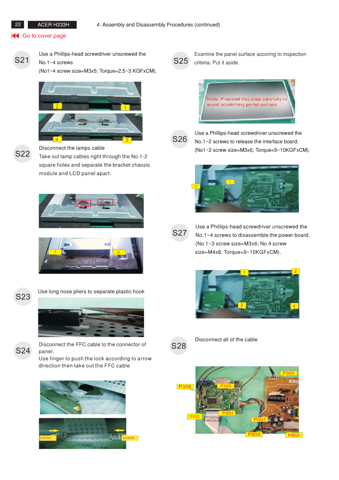
S21 | No.1~4 screws | S25 criteria. Put it aside. |
(No1~4 screw size=M3x5; Torque=2.5~3 KGFxCM).
2 | 1 |
|
|
|
| Use a |
| 4 | 3 | S26 No.1~2 screws to release the interface board. |
S22 | Disconnect the lamps cable |
| (No1~2 screw size=M3x6; Torque=9~10KGFxCM). |
|
| ||
Take out lamp cables right through the |
| ||
square holes and separate the bracket chassis module and LCD panel apart.
1
2
1 | 2 |
Use long nose pliers to separate plastic hook
S23
Disconnect the FFC cable to the connector of
S24 panel.
Use finger to push the lock according to arrow direction then take out the FFC cable
Use a
S27 No.1~4 screws to disassemble the power board.
(No 1~3 screw size=M3x6; No 4 screw size=M4x8; Torque=9~10KGFxCM).
1 | 2 |
|
3 | 4 |
|
Disconnect all of the cable
S28
P003
P308P309
P301
FFC
P001
P805P802
